1. Incline Conveyor Belt for Limited Spaces
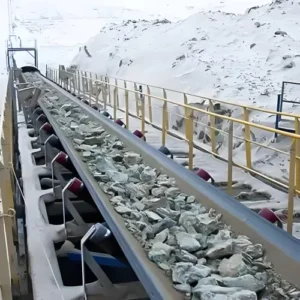
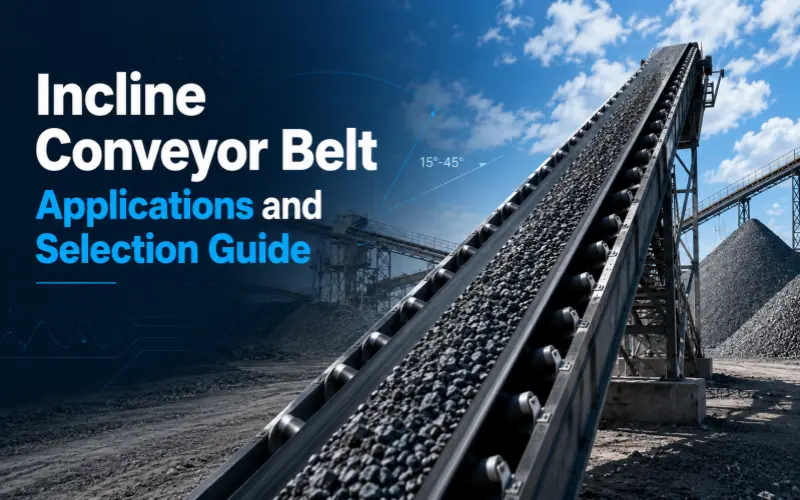
An incline conveyor belt helps you lift bulk materials to higher processing points when mining, quarrying, construction, or recycling sites have limited space. Extending a horizontal conveyor can increase route length, occupy more floor area, and restrict where you place crushers, screens, hoppers, or other equipment.
2. Need for an Incline Conveyor Belt
A few isolated particles can remain within normal bulk movement, provided the load continues steadily and stays inside the effective carrying width. Selection becomes necessary when movement expands across the load, repeats during operation, or forces you to reduce feed rate, adjust speed, or stop the conveyor for correction. At that point, an incline conveyor belt must provide surface grip, retention, or containment suited to the material, incline, and capacity.
2.1 Incline Conveyor Belt Load Behavior
On a horizontal conveyor, most material weight acts toward the belt surface, helping friction and particle interaction hold the load. As the conveyor rises, gravity creates a stronger downslope pull. An incline conveyor belt must manage sliding, rolling, load shifting, and spillage during start-stop cycles. Changes in conveyor geometry can alter material behavior even when belt width, speed, and capacity remain unchanged, so the inclined section requires separate performance evaluation.
2.2 Incline Conveyor Belt Stability Thresholds
Conveying stability assessment begins with the scale, frequency, spread, and operating effect of material movement. Repeated rolling, sliding, or layer shifting across a meaningful portion of the load indicates declining control, especially when it causes rollback, spillage, capacity loss, or reduced feed. Particle size also changes the risk. Movement among fine particles may remain localized, while one large lump rolling backward can create impact risk and justify immediate corrective action.
3. Incline Conveyor Belt Applications
3.1 Crushing and Screening Lines
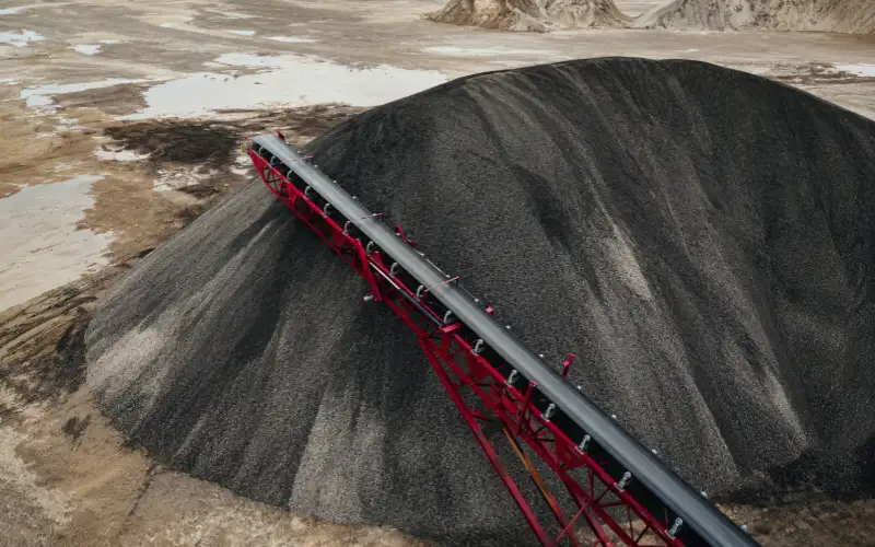
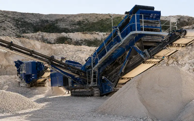
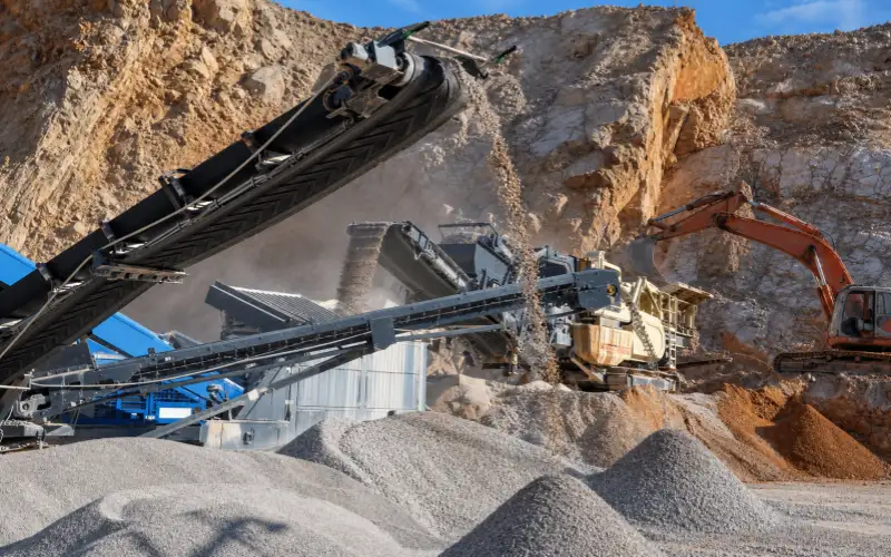
In a crushing line, the crusher discharge and the next screen are often set at different elevations. When the floor run is short, the conveyor has to climb soon after material leaves the crusher. An incline conveyor belt is installed in this position. It carries the discharge straight to the screen in one transfer and saves floor space in crowded areas where several crushers, screens, and chutes sit close together.
3.2 Hopper and Silo Feeding
A hopper or silo inlet is often several meters above the feed conveyor. An incline conveyor belt can take material from the lower line and deliver it directly into the inlet. The same layout is used to feed elevated bins, dosing equipment, and stockpile conveyors. On site, its start and discharge points are fixed by the building, access platforms, and the machinery already operating nearby. Maintenance access also needs space.
3.3 Truck and Port Loading
Truck loading starts with one fixed requirement. The discharge point has to sit above the truck bed. An incline conveyor belt begins beside the ground-level feed point and runs up along the edge of the loading lane. Trucks can then drive underneath and line up with the discharge chute. Warehouses use a similar arrangement at raised receiving bays, and ports use it to reach loading points above trucks or vessels.
3.4 Plant Retrofits
A retrofit usually starts with fixed building limits and equipment already installed in established positions. A new hopper, platform, or process stage may sit above the original conveyor, leaving only a short run for elevation. An incline conveyor belt lets the transfer fit inside that space while preserving access for maintenance and vehicle movement. Once the route is fixed, material behavior becomes the next input for choosing the belt structure.
4. Material Characteristics and Incline Conveyor Belt Performance
Material behavior sets the practical limit of an incline conveyor belt and provides the basis for selecting its carrying surface and structure.
4.1 Particle Size and Load Behavior
A large rock and a bed of small crushed stone place different demands on an incline conveyor belt. Large pieces create concentrated impact and may roll from a few contact points. Smaller particles form a deeper bed with more contacts. Fine material can move as a layer, especially during loading or speed changes. Record the maximum lump size together with the normal particle range before selecting the belt surface structure.
4.2 Particle Shape and Movement
Rounded gravel, pellets, and beans can rotate easily when gravity pulls them down the slope. Angular particles have more contact points and may lock against neighboring pieces, although their sharp edges can increase cover wear. Flat or elongated pieces may overlap, turn, or bridge during loading. Particle shape therefore changes both movement and loading pattern. Feed direction and bed depth can make these differences more pronounced during continuous plant operation.
4.3 Surface Texture and Grip
Two materials with similar size and weight can begin moving at different incline angles because their surfaces contact the belt differently. Smooth particles have less grip and may start rolling or sliding earlier. Rough particles resist movement more effectively, yet dust, polishing, or wear can change that behavior over time. Check the material surface together with the belt cover condition, especially when the existing conveyor performs differently after extended service.
4.4 Particle Size Distribution
Average particle size can hide the part of the load that controls performance. A uniform 20 mm product packs differently from a mixed 0–100 mm feed containing fines and large lumps. Maximum lump size sets impact and clearance needs, while the full size distribution affects packing, segregation, and layer movement. Provide both values so the selected belt structure matches the material that actually reaches the conveyor during normal daily operation.
4.5 Moisture and Operating Effects
Moisture changes how particles interact with the belt and with one another. Provide the moisture percentage when test data is available. Site observations can describe the remaining conditions: visible free water, clumps forming in the feed, material sticking to the belt or chute, and buildup on the return side. Rainfall, washing, or process water should also be identified when it changes material behavior during a shift or between operating seasons.
4.6 Bulk Density and Lump Weight
Bulk density and individual lump weight affect parts of the design. Bulk density, loading depth, belt width, and speed determine how much mass the conveyor carries continuously. A large lump adds a concentrated load when it lands and may damage the cover or carcass. Give both the bulk density and the maximum lump weight when the feed contains oversize pieces. This helps define carrying strength, impact protection, and loading control.
4.7 Rolling Sliding and Load Shifting
Material returning down an incline can move in three recognizable ways. Rolling occurs when individual particles rotate. Sliding occurs when particles travel against the belt surface with little rotation. Flowing or shifting occurs when part of the loaded bed rearranges and moves downslope. Watch which pattern appears, where it begins, and how much of the load it affects. That observation gives clearer guidance for choosing grip, cleats, or side containment.
5. Incline Angle and Conveyor Belt Requirements
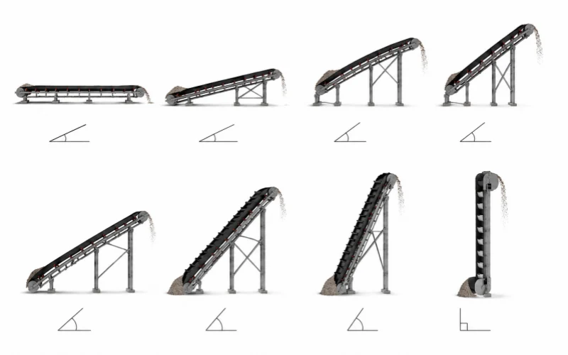
Angle increases the downslope force acting on the load. Belt requirements then progress from surface grip to material retention and structural containment.
5.1 Maximum Incline Depends on Operating Conditions
The maximum workable incline comes from the combined behavior of the material, belt surface, belt structure, loading depth, speed, and capacity. At the same 20° incline, large angular rock may settle into a stable bed, while small rounded gravel can begin rolling. Moisture or an uneven feed can change the result again. Use the angle as one design input and confirm it against the full operating condition during normal production.
5.2 Low Inclines and Surface Grip
At a low incline, a smooth rubber belt may still carry the load steadily when particles have low rolling tendency, the feed is centered, and loading depth remains controlled. Startup and stopping behavior should remain stable. If the material stays within effective carrying width at required capacity, extra profiles may add little value. The decision should come from observed movement and operating margin after changes in moisture or feed rate.
5.3 Moderate Inclines and Material Movement
As the angle increases, small changes in particle shape, moisture, and feed distribution have a larger effect on movement. Rolling may begin at the upper surface of the load, sliding may develop near the belt, or part of the bed may shift during startup. This stage requires checking how often movement occurs, how much material is affected, and whether the conveyor can reliably maintain the required capacity without repeated correction.
5.4 Higher Inclines and Material Retention
At a higher incline, increasing surface friction alone may leave part of the load free to move. The selection focus moves toward holding the material at intervals along the belt. Profile height, spacing, loading depth, maximum lump size, and discharge clearance then work together. This is the point to evaluate profiled or cleated arrangements according to the actual movement, while keeping the chosen structure compatible with pulleys and return-side support.
5.5 Steep Inclines and Structural Containment
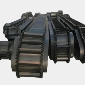
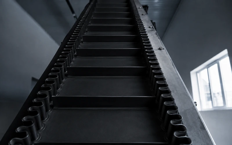
Steep conveying requires a belt system that forms and carries a defined material pocket. The design has to control the load at the base, along the incline, and through discharge. Sidewalls, cross cleats, loading geometry, and return arrangements become part of one retaining structure. A sidewall conveyor belt is one option for this duty, particularly where available floor run is short and required lift is high in the existing plant.
Confirmed Operating Condition | Belt Structure to Assess | Details to Confirm |
Cartons, bags, or unit loads slide against a smooth belt surface | Package base material, unit weight, start-stop frequency, and surface contamination | |
Loose particles roll or a shallow material bed shifts downslope | Particle size and shape, profile height, loading depth, discharge, and cleaning | |
Material requires positive support at regular intervals along the incline | Cleat height, cleat spacing, loading depth, lump size, and return-side clearance | |
A steep incline causes edge spillage or requires a deeper loading section | Sidewall height, cleat structure, effective belt width, transition arrangement, and return travel |
6. Control Rollback and Spillage on an Incline Conveyor Belt
Trace rollback and spillage to the first unstable point before changing the belt width, surface, or retaining structure.
6.1 Check the Loading Point
Watch the material from the chute outlet until it settles on the belt. A stable load should enter near the center and form an even bed before reaching the incline.
- Landing position— Check whether the material falls near the belt center or consistently loads one side.
- Feed direction— Check whether the material enters along the direction of belt travel or strikes the belt sideways.
- Drop height— Look for bouncing, rolling, or separation immediately after impact.
- Peak flow— Observe short surges as well as the average hourly feed. Brief overloads can trigger rollback and edge spillage even when average capacity appears acceptable.
6.2 Measure Effective Loading Width
Effective loading width = nominal belt width − edge clearance − space occupied by sidewalls or other edge structures
Measure the actual material bed after loading, through the incline, and during peak feed. Record the maximum sideways movement and the remaining clearance at both edges. Material that reaches the edge only during surges points to unstable feeding or excessive loading depth. A load that occupies nearly all usable width during steady operation requires a review of belt width or side containment.
6.3 Inspect Wear and Buildup
Material loss that begins in one section of the incline often indicates a local change in the belt surface or retaining structure. Inspect the complete carrying path for:
- Polished or hardened cover rubber
- Uneven loss of chevron profile height
- Cracked, bent, or damaged cleats
- Split, folded, or worn sidewalls
- Material packed between profiles or against retaining structures
- Local damage around the bases of attached cleats or sidewalls
Compare the affected section with a less-worn area. Record where the loss starts and whether it continues after the damaged section has passed.
6.4 Trace the First Point of Material Loss
Later spill points may result from a problem that begins farther upstream. Use the first visible loss point to decide where corrective work should start.
Observed Pattern | First Area to Check | Initial Direction |
Material is already unstable before the incline | Chute outlet, landing position, feed direction, and drop height | Stabilize and center the incoming stream |
The load fits at entry and gradually reaches the belt edge | Loading depth, effective width, and sideways movement | Reduce peak loading or review available carrying width |
Rollback or spillage begins at a visibly worn section | Cover rubber, profiles, cleats, or sidewalls | Restore the required surface or retaining condition |
The loss position changes as the belt moves sideways | Belt tracking, skirts, and transition area | Correct alignment and loading position |
Material loss occurs only during brief production peaks | Feeder output and instantaneous flow | Control surge loading before changing the belt specification |
7. Incline Angle and Conveyor Capacity
Usable capacity depends on the material cross-section that remains stable on the incline, together with belt speed and bulk density.
7.1 Nominal Capacity and Usable Capacity
Belt width alone does not establish the capacity of an incline conveyor belt. The calculation needs to use the loaded cross-section that can travel within the available edge clearance and the carrying height provided by the belt structure.
Usable mass flow = stable loaded cross-section × belt speed × bulk density × unit conversion
The stable loaded cross-section may be limited by the incline angle, feed condition, material movement and the available containment structure. Peak flow should also be checked because a short surge can temporarily produce a deeper or wider load than the normal operating condition.
7.2 Particle Size Changes the Usable Load
The same belt width and speed can produce different usable capacities when the feed composition changes.
Feed condition | Effect on the loaded cross-section | Capacity consideration |
Uniform particle size | Produces a relatively consistent loading profile | Capacity can be estimated from a stable and repeatable cross-section |
Mixed fine and coarse material | May segregate during loading and travel | Confirm whether fines and larger particles remain inside the intended loading area |
Large individual lumps | Reduce the space available for surrounding material | Check lump clearance, impact position and the distance from belt edges |
Irregular feed surges | Temporarily increase loading depth or width | Use peak feed conditions when checking containment and available belt area |
Average particle size cannot represent all four conditions. Maximum lump size, normal particle range and peak feed pattern should therefore remain separate inputs in the capacity check.
7.3 Confirm Belt Speed With the Complete System
Increasing belt speed raises theoretical throughput, but it also changes loading, material travel and discharge behavior. The selected speed needs to work with the complete conveyor arrangement.
Check the following conditions together:
- Whether incoming material can enter the belt at a compatible direction and speed
- Whether acceleration causes rolling, sliding or load separation
- Whether the selected belt structure provides sufficient support between profiles or cleats
- Whether the discharge chute can receive the material at the resulting trajectory
- Whether cleaning and return-side operation remain manageable
A speed increase is accepted only after the required output and stable material travel have been confirmed together.
8. Confirm the Incline Conveyor Belt Specification
After the belt structure has been selected, every dimension, material and performance requirement must be converted into a manufacturable order specification.
8.1 Convert the Selection Into Product Data
Descriptions such as “incline belt” or “high-profile belt” leave important manufacturing details undefined. The confirmed specification should record:
- Finished belt width and supplied length
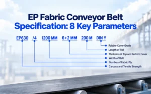
- Carcass material, tensile rating and number of plies
- Top and bottom cover grade and thickness
- Selected surface pattern or material-retention structure
- Profile or cleat height, shape, orientation and spacing
- Sidewall type, height and arrangement when included
- Open or endless supply condition
- Agreed splice preparation or joint construction
- Applicable standard and required heat, oil, flame, abrasion, chemical or anti-static performance
Customized profiles, cleats and sidewalls should be connected to an approved drawing. This keeps dimensions and arrangement clear when the written description alone cannot fully define the structure.
8.2 Check the Specification Against the Conveyor
The confirmed belt still needs to fit the existing conveyor and its surrounding components.
Belt detail | Conveyor condition to verify | Purpose of the check |
Finished belt width | Pulley face, carrying rollers, frame and chute clearances | Keep the belt inside the available running space |
Carcass thickness and flexibility | Pulley diameters, troughing arrangement and transition sections | Confirm that the selected construction can flex through the conveyor path |
Profile or cleat dimensions | Return support, cleaners, skirt boards and discharge area | Check that raised structures can pass without interference |
Sidewall dimensions | Loading chute, discharge chute and lateral clearances | Preserve the required material path and available loading space |
Endless length or supplied length | Conveyor center distance and take-up travel | Confirm installation length and available tension adjustment |
Available installation space and conveyor arrangement | Select a joint that can be completed and operated on the actual conveyor |
An existing belt can provide useful dimensional references. Measurements should be taken from identifiable specification markings, drawings or confirmed equipment dimensions, especially when the removed belt has stretched, worn or been repaired.

9. Select the Incline Conveyor Belt for the Complete Application
The final choice should reflect how the actual material behaves throughout the conveyor route. Particle size, shape, moisture and bulk density describe the load, while incline angle, feed condition and required capacity define the forces and loading conditions acting on it.
These inputs determine the level of surface grip, material retention and side containment required from the belt. They also establish the carrying width, carcass, cover and raised structures that must remain compatible with the conveyor. Evaluating the complete application provides a clear basis for selecting an incline conveyor belt that can carry the required load from the lower feed point to the upper discharge point.
Send the available material information, conveyor layout and required capacity for technical review. These details can be used to determine the suitable belt structure and identify any specifications that still require confirmation.
10. Incline Conveyor Belt FAQs
These questions cover installation and specification details that remain after the carrying structure has been selected.
10.1 Does a Chevron Conveyor Belt Need a Confirmed Running Direction?
Yes. A chevron conveyor belt used for incline conveying has a defined carrying direction from the lower feed point to the upper discharge point. The order and drawing should mark this direction because the profile layout, loading position, splice and discharge arrangement are based on it. The belt returns through the lower run as part of its continuous loop, but this return movement does not create bidirectional material conveying.
10.2 Can a Profiled Incline Conveyor Belt Use Mechanical Fasteners?
Yes, some profiled belts can use mechanical fasteners. Suitability depends on belt thickness, tensile rating, pulley diameter, fastener type and the available profile-free splice area. The completed joint must pass through the conveyor without interfering with the raised profiles, return support or surrounding structures. The splice arrangement should be confirmed before the profile layout and supplied belt length are finalized.
10.3 Should the Horizontal-to-Incline Transition Be Included in the Specification?
Yes. The transition changes belt curvature, belt support and the way material settles before entering the inclined section. Provide its length or radius, roller and pulley positions, and the support arrangement in this area. These details are used to check carcass flexibility and clearance for profiles or cleats. Incline angle and lift height alone cannot describe the complete belt path.
10.4 Can a Thicker Incline Conveyor Belt Directly Replace the Existing Belt?
No. A thicker belt may require larger pulley diameters and may respond differently at troughing and transition sections. It can also change the available take-up range and clearance around raised profiles. Before increasing carcass or cover thickness, check the existing pulleys, support arrangement, tensioning travel and splice method. Additional thickness should correspond to a confirmed strength, impact or wear requirement.
10.5 Does an Endless Incline Conveyor Belt Need a Defined Length Measurement Method?
Yes. The order should state the agreed measurement method, measurement condition and length tolerance. A used endless belt may already have permanent elongation, so its measured circumference should be checked against the take-up position, conveyor center distance and original belt records. This helps keep the replacement within the available installation length and tension-adjustment range.
10.6 Can an Incline Conveyor Belt Run Flat or Troughed?
Yes, both arrangements are possible. The suitable option depends on belt construction, material cross-section, support geometry and the clearance required by profiles, cleats or sidewalls. The belt must flex through every transition while its raised structures maintain a clear return path. Mark the flat sections, troughed sections and transition positions before confirming the carcass and carrying structure.