1.How the Calculation Works
To calculate conveyor belt length, first trace the complete belt path and confirm whether the conveyor uses a simple two-pulley layout. Measure the center distance and the diameters of the drive and tail pulleys in the same unit. For a two-pulley conveyor, combine twice the center distance, the pulley-wrap length, and any correction for unequal diameters. This gives the theoretical endless length, which you should then verify against the take-up position and splice requirements before ordering.
2. Identify Your Complete Conveyor Belt Path
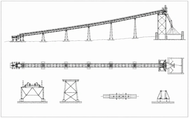
Before you begin any conveyor belt length calculation, I recommend tracing the complete closed-loop path of your conveyor belt. If your mining conveyor follows changing terrain, one center distance cannot represent its actual length. You need to divide the route into:
- Carrying-side straight and curved sections
- Return-side straight and curved sections
- Pulley wrap sections
- Take-up and auxiliary pulley sections
You can use the standard two-pulley conveyor belt length formula only when both sides can be approximated as straight paths.
2.1 Trace Your Carrying-Side Route
Start at the tail pulley and follow the conveyor belt centerline to the head pulley. You should mark every point where the route changes slope or direction. These points may include horizontal sections, inclines, declines, convex curves, concave curves and horizontal turns.
If your drawing provides only horizontal distances, you also need the elevation at each point where the conveyor route changes in gradient. The horizontal distance and elevation difference between adjacent points allow you to calculate the actual length of each inclined section rather than using its shorter horizontal projection. For vertical curves, use the specified curve radius and angle to calculate the arc length.
2.2 Trace Your Return-Side Route
Next, trace the conveyor belt from the head pulley back to the tail pulley. You should calculate this route separately because the return side may pass around bend pulleys, snub pulleys, take-up pulleys, intermediate drives or belt turnover sections.
Simply doubling the carrying-side length may omit these additional sections. When we check a replacement length, we normally compare the return-side layout with the current take-up position before confirming the complete loop.
2.3 Include Every Curve and Pulley Wrap
For each curved section, you need its radius and change in direction to determine the arc length. For every pulley contacted by the conveyor belt, you need its diameter and actual wrap angle. The belt length around each pulley depends on both values. For pulleys of the same diameter, a 90-degree wrap adds only half the arc length of a 180-degree wrap.
The general relationship is:
Lendless=Lcarrying path+Lreturn path+∑Lpulley wrap
This relationship gives you the correct starting point for a complex conveyor belt calculation. For long mining conveyors, I recommend using the profile drawing, pulley layout and take-up arrangement together. Professional design tools also define exact pulley positions, wrap angles and curve locations when calculating the complete geometry.
3. Required Data for Conveyor Belt Length Calculation
A usable conveyor belt length calculation needs measured geometry, not a general equipment description. I recommend creating one calculation record for the complete conveyor. Every coordinate, pulley dimension and take-up position should come from the same drawing revision or the same field survey.
3.1 Build a Route Coordinate Sheet
Choose one coordinate origin and follow the conveyor belt in its running direction. Assign a point number whenever the route reaches a pulley center, changes slope, enters a curve or changes horizontal direction.
For each point, record:
- Point identification
- Horizontal station or X coordinate
- Lateral Y coordinate when the route turns
- Elevation Z
- Connected component or route section
For two adjacent points, a straight three-dimensional section can later be calculated from:
Li = √((ΔX)2 + (ΔY)2 + (ΔZ)2)
Li=(ΔX)2+(ΔY)2+(ΔZ)2
A simple two-pulley conveyor may require only the head and tail pulley centers. A mining conveyor needs every intermediate control point. Measure from the conveyor belt centerline and pulley axes. Frame ends, walkways and ground distances do not define the running path.
3.2 Record Curve Geometry
Mark the beginning and end of every convex, concave or horizontal curve. If the design uses a circular curve, record its radius R and total direction change θ. The later arc-length calculation will use:
Lcurve=Rθ
Here, θ must be converted to radians.
If the radius or angle is unavailable, extract the conveyor belt centerline length directly from the CAD or DXF drawing. Using only the two curve endpoints produces the chord length, which is shorter than the actual arc.
When you estimate a curve from surveyed points, identify the result as an approximation. More closely spaced points follow the curve more accurately, while widely spaced points can understate its length.
3.3 Measure the Working Pulley Diameter
Record the diameter at the surface contacted by the conveyor belt. A drawing may show the steel-shell diameter before lagging is added. If the lagging thickness is t, the working diameter is:
Dworking=Dshell+2t
For an installed pulley, you can measure its circumference U at the contact surface and calculate:
Dworking=π/U
Identify every diameter with its pulley number. Do not record only the drive and tail pulleys when the route also contains bend, snub or take-up pulleys. For a replacement project, confirm whether the calculation should use the original design diameter or the current worn diameter.
3.4 Determine Each Pulley Wrap Angle
Draw or identify the straight tangent line entering the pulley and the tangent line leaving it. The change between these two belt directions determines the actual wrap angle.
Record the angle for every pulley in degrees or radians. A snub pulley may increase the drive-pulley wrap, while a take-up arrangement can create several different contact angles. Applying 180° to every pulley can overstate or understate the total length.
3.5 Fix the Take-Up Reference Position
Record the take-up pulley center at the time of measurement. Then mark its intended position when the new conveyor belt is installed. You also need the travel direction, total stroke and remaining movement on both sides of that position.
In a common arrangement with two belt sections connected to one moving take-up pulley, a movement of x changes the loop length by approximately 2x. Other arrangements may affect more sections or use angled paths, so you need to recalculate their actual geometry.
3.6 Keep One Measurement Condition
Do not combine original curve data, worn pulley diameters and a current take-up position without documenting the differences. Create separate design and field records when the installed conveyor no longer matches its original drawing.
For field measurements, record the date, loading condition, operating status and take-up position. Select the target installation condition before calculating the required closed-loop length. Splice preparation and installation allowances should be evaluated separately after the geometric length is established.

4. Conveyor Belt Length Formula
You can use an approximate formula when the conveyor has two end pulleys and two straight belt runs. If your mining conveyor follows changing terrain or contains additional belt-deflecting pulleys, calculate the actual belt path from its approved drawings.
This keeps the conveyor belt length calculation practical while accounting for the real conveyor layout.
4.1 Simple Two-Pulley Formula
Use this formula for an open layout with two end pulleys, parallel shafts and no additional bend, snub or take-up pulleys that change the belt path:
L≈2C+π(D1+D2)/2+(D1−D2)2/4C
Where:
- L = theoretical endless conveyor belt length
- C = center distance between the two pulley shafts
- D1 = effective working diameter of the drive pulley
- D2 = effective working diameter of the tail pulley
- π = approximately 3.1416
The first term represents the two straight belt runs. The second represents the combined pulley sections, while the final term corrects for unequal pulley diameters.
Use the same unit for every value. If C is measured in meters, convert both pulley diameters to meters before calculating. Use diameters measured over any pulley lagging and follow the same belt reference line on both pulleys.
This method applies only when the carrying and return sides are approximately straight. Bend, snub and take-up pulleys change the conveyor belt path and must be included separately.
4.2 Equal Pulley Formula
If the drive and tail pulleys have the same effective working diameter:
D1=D2=D
The correction term becomes zero, so the formula simplifies to:
L=2C+πD
This is the quickest way to calculate conveyor belt length for a basic two-pulley layout. The result is the theoretical endless length at the measured center distance and selected take-up position.
4.3 Long Mining Conveyor Routes
For a long mining conveyor, you usually do not need to calculate every slope and curve manually. Obtain the carrying-side and return-side belt-path lengths from approved profile, plan, CAD or 3D drawings.
Use the profile drawing for elevation changes. If the conveyor also curves horizontally, include its plan alignment or complete 3D belt path.
The calculation follows this relationship:
Ltotal=Scarry+Sreturn+∑Lwrap
Where:
- Scarry = carrying-side path length
- Sreturn = return-side path length
- ∑Lwrap = combined wrap length around all pulleys
Measure the carrying-side and return-side paths between pulley tangent points so they exclude the pulley arcs. Then add the actual wrap length around every head, tail, bend, snub and take-up pulley.
If the CAD drawing already traces the complete closed belt reference line, use that measured length directly. Do not add the pulley wrap lengths again.
Place the take-up pulley at its specified installation position before measuring the path. Reserve sufficient travel for initial tensioning and future conveyor belt elongation.
If the installed conveyor differs from its drawing, use updated survey data or ask the conveyor designer or site engineer to verify the revised layout. Provide the conveyor drawings, pulley diameters, take-up arrangement and splice details.
The result represents the finished endless conveyor belt length. If the belt will be supplied open for field splicing, add the required splice allowance to determine its manufacturing or supply length.
This path-based method is more reliable than applying the two-pulley formula to a complex mining conveyor route.

5. How to Calculate Conveyor Belt Length
Before starting the arithmetic, decide whether your conveyor matches the simple two-pulley layout. If it contains changing slopes, curved sections or additional pulleys, use the centerline lengths from its drawing. A precise conveyor belt calculation based on the wrong layout will still produce the wrong length.
Step 1: Select the Calculation Method
Use the two-pulley formula when your conveyor has:
- One drive pulley
- One tail pulley
- Two approximately straight runs
- No bend, snub or take-up pulleys in the path
For a long mining conveyor, use the carrying-side and return-side centerline lengths from the profile, CAD or DXF drawing. Confirm that the drawing represents the current pulley layout and target take-up position.
Step 2: Use One Measurement Unit
Write down C, D1 and D2 for a simple layout. Convert them into the same unit before entering the formula.
For example:
If the center distance is recorded in meters, both pulley diameters must also be converted to meters. Keep drawing-based route lengths and pulley measurements in that same unit.
Step 3: Calculate the Straight Sections
For a simple two-pulley conveyor, the carrying and return runs are each approximately equal to C. Their combined length is:
Step 4: Calculate the Pulley Contribution
For the simple layout, calculate the combined pulley term:
Add the two pulley diameters, multiply the result by π, and divide by 2.
For a complex route, include the path around every drive, tail, bend, snub and take-up pulley. If your CAD centerline already includes these arcs, do not add them again.
Step 5: Add the Diameter Correction
When the drive and tail pulley diameters differ, calculate:
If both pulleys have the same diameter, this value becomes zero. You can skip the correction and use the equal-pulley formula.
Step 6: Calculate the Theoretical Endless Length
For the simple layout, add the three results:
For a drawing-based mining conveyor, add the carrying-side length, return-side length and any pulley sections not already included in the centerline.
The result is the theoretical endless length at the selected geometry. Before using it for an order, verify the take-up position and confirm whether the belt will be supplied endless or prepared for field splicing.

6. Conveyor Belt Length Calculation Example
This example shows how to calculate conveyor belt length for a simple two-pulley conveyor. It does not apply to a mining conveyor with additional pulleys or a curved route. Use the drawing-based method for those layouts.
Parameter | Value |
Center distance C | 50 m |
Drive pulley diameter D1 | 1000 mm |
Tail pulley diameter D2 | 800 mm |
Step 1: Convert the Units
Convert both pulley diameters from millimeters to meters:
1000mm = 1.0m
800mm = 0.8m
The values used in the calculation are therefore:
- C=50 m
- D1=1.0 m
- D2=0.8 m
Step 2: Calculate the Straight Length
The conveyor has one carrying run and one return run:
Lstraight=2 x 50=100m
The two straight sections contribute 100 m to the theoretical endless length.
Step 3: Calculate the Pulley Length
Insert the two pulley diameters into the pulley term:
The belt sections around the drive and tail pulleys contribute approximately 2.8274 m.
Step 4: Calculate the Correction
The pulley diameters differ by 0.2 m, so include the correction term:
The correction is small in this example because the pulley diameter difference is small compared with the 50 m center distance.
Step 5: Calculate the Final Length
Add the straight length, pulley length and correction:
The calculated endless conveyor belt length is approximately 102.83 m. This is the theoretical closed-loop length. Check the take-up position and splice requirements before using the result as the final cutting or ordering length.

7. Adjust the Calculated Length for Installation
The result from the conveyor belt length formula is the theoretical endless length at the measured pulley positions. Before you place an order, you still need to confirm the take-up reference position and the field-splice requirements.
7.1 Set the Take-Up to the Intended Installation Position
A replacement conveyor belt should not be measured with the take-up at either end of its travel. Otherwise, you may have insufficient movement available to tension the belt or compensate for elongation after commissioning.
I recommend placing the take-up at the installation position specified in the conveyor drawing. If that information is unavailable, record its current position and remaining travel, then send these details to the belt supplier for review.
For conveyors with a moving take-up pulley, its position forms part of the actual belt path. The pulley position should therefore be included in the conveyor belt calculation rather than treated as an arbitrary extra allowance.
7.2 Confirm the Required Splice Allowance
For a belt supplied open and spliced on site, the ordered open length may be greater than the required finished endless length. Part of the material is used to prepare the splice.
The required allowance depends on:
- Fabric or steel cord construction
- Belt strength and number of plies
- Step length and splice angle
- Hot or cold splicing method
- Splice design supplied by the manufacturer
A fixed percentage or standard number of metres should not be applied to every conveyor belt. A steel cord splice on a long mining conveyor can require a very different preparation length from a multi-ply fabric belt.
7.3 Specify the Length Clearly When Ordering
Your purchase specification should state whether the quoted dimension is:
- Finished endless length:the circumference after the splice is completed
- Open length:the supplied length before the field splice
- Open length including splice allowance:the prepared supply length required to achieve the specified endless length
For an existing mining conveyor, provide the theoretical endless length, take-up arrangement, take-up position and approved splice drawing. This gives the manufacturer enough information to determine the correct production length without adding an uncertain general allowance.
8.Conclusion
To calculate conveyor belt length accurately, use a method that matches the actual conveyor. The two-pulley formula suits a simple straight layout, while conveyors with additional pulleys or changing terrain require the complete centerline path from the drawing. Keep all measurements in one unit, use the correct pulley dimensions, and distinguish the theoretical endless length from the production length required for installation and splicing.
9.Conveyor Belt Length Calculation FAQ
Will Factory Testing Reduce the Belt Length I Receive?
No. We confirm only the ordered length with you before production. We account internally for the additional material needed for routine factory sampling, so you do not need to specify a test-sample allowance. The finished shipment follows the confirmed order length, while the sampling section is handled within our production arrangement and is not deducted from the quantity you ordered.
Should I Round the Calculated Length before Sending an RFQ?
Keep the unrounded result in your calculation record and state the intended order length separately. You should not automatically round every result to the nearest meter because several rounded sections can create a larger cumulative difference. If the decimal portion is meaningful for installation, send us both the calculated value and proposed order length. We will confirm which figure will control production.
Can I Check a Rolled Belt’s Length without Fully Unrolling It?
You can estimate the remaining length from the coil dimensions and belt thickness, but tightly wound layers may compress and the roll may not remain perfectly circular. Treat this result as an incoming inspection estimate. If it indicates a material shortage, compare it with our production records and use an agreed direct measurement method before deciding whether the delivered length is incorrect.
Can You Split My Required Length into Several Rolls?
Yes. If you already know the required length of each roll, send us your division plan. If individual roll lengths are undecided, provide the maximum allowable weight per roll. We will calculate a practical division and confirm it with you. We also review the planned reel size for export handling and will notify you if the arrangement may exceed applicable limits.
Can I Keep the Previous Production Length When Changing to a Thicker Belt?
You should not confirm it from the previous order alone. A thicker construction changes where the belt’s reference line runs around each pulley, and the difference can become relevant with smaller pulleys or several bends. We would compare the new belt structure with your conveyor geometry before confirming the production length, especially when the replacement also changes the carcass type.
Do I Need to Add Length for Troughing and Transition Sections?
Normally, we do not add a separate longitudinal allowance only because the belt changes from flat to troughed. Your calculated order length follows the conveyor centerline. Transition design still matters because the belt edges and center pass through different three-dimensional paths and experience different strain. We review the transition distance for belt performance, but we do not convert it into a general extra-length value.