1.Conveyor Belt Design Essentials You Need to Know
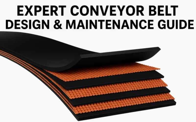
If conveyor belts could talk, they’d probably have some choice words for the industrial world—after all, carrying tons of rock, coal, and iron ore every day isn’t exactly the dream job. But jokes aside, the real conversation here is about understanding what goes into robust conveyor belt design. If you’ve ever wondered why some conveyor belts run for years without issues, while others quit faster than an intern on day one, the answer lies beneath the surface—in the carefully layered structure that makes a conveyor belt durable and reliable.
Conveyor belts in heavy industries like mining, construction, cement production, and steel manufacturing aren’t made from luck—they’re engineered layer by layer for survival. Let’s peel back these layers without metaphors this time (because let’s face it, even the toughest engineers tire of endless analogies) and dig straight into what matters most in a serious-but-still-smiling tone.
1.1 Top Cover Layer – Not Just Another Pretty Face
The top cover is literally the belt’s frontline. It directly interacts with abrasive, sharp, and heavy materials—think crushed rock, minerals, or metallic ores constantly scraping and pounding away at the surface. This constant interaction demands exceptional abrasion and impact resistance. If the top cover is too thin, the consequences are predictable: the belt surface wears prematurely, the carcass becomes exposed, and inevitably, significant damage follows. This domino effect means unscheduled downtime, hefty repair bills, and angry phone calls nobody enjoys making.
For heavy-duty environments, the top cover thickness typically ranges between 6 mm to 12 mm. This thickness isn’t random; it’s based on data gathered from years of operational experience. Industry studies by Conveyor Equipment Manufacturers Association (CEMA) suggest a minimum of 8 mm thickness for belts handling sharp-edged materials, significantly extending operational life.

1.2 The Carcass – More Important Than It Sounds
Next up is the carcass, the conveyor belt’s structural backbone. Here’s a fun fact: despite the name, there’s nothing sinister about the carcass—it’s all about resilience and strength. Made from fabrics like Polyester-Nylon (EP), Nylon-Nylon (NN), or even robust steel cords (ST), this middle layer provides critical tensile strength, flexibility, and stability. Choosing the right carcass material isn’t guesswork—it’s about knowing exactly how your belt will be used.
For example, EP carcasses are great for general industrial use, offering balanced flexibility and tensile strength, with a typical strength rating ranging between 200 N/mm to 2000 N/mm. Steel cord belts step things up dramatically, offering tensile strengths from 1000 N/mm to over 10,000 N/mm. Why does this matter? Because insufficient tensile strength in the carcass isn’t just annoying—it’s disastrous. Imagine heavy ores piling onto a belt with inadequate tensile strength. The belt stretches unevenly, stress points form, and sooner or later, catastrophic belt tears become inevitable.

1.3 Bottom Cover Layer – Quiet but Crucial
While the bottom cover doesn’t get as much attention as the top, underestimate it at your peril. It quietly interacts with pulleys, idlers, and drive rollers every single second. A bottom cover that’s too thin rapidly heats up from friction, weakening the rubber and risking delamination of layers. On the other hand, a bottom cover that’s too thick adds unnecessary weight, increasing energy consumption and reducing overall efficiency.
Heavy industrial belts typically require bottom covers between 2 mm and 6 mm thick. The choice depends heavily on the belt’s speed, load, and pulley diameter. Getting it right is like hitting the sweet spot: lower maintenance, reduced wear, and optimized performance.

1.4 Extra Structures – Sometimes You Need More Than Basic
Beyond standard layers, heavy-duty conveyor belts often require extra reinforcements. Consider these additional features:
- Breaker layers:Additional layers that boost impact resistance, especially valuable at high-drop material loading points.
- Anti-tear fabrics:Strategically woven into the carcass to enhance lateral tear resistance, critical in mining or quarrying operations.
- Sidewalls and cleats:Essential for steep incline transport, ensuring materials stay firmly on the belt rather than spilling everywhere (because cleaning up spillage isn’t anyone’s favorite pastime).
According to recent data from the International Material Handling Association (2024), incorporating these enhancements reduces downtime caused by belt damage by around 20%. Less downtime means happier bosses, fewer headaches, and more profit—something everyone in the industrial world can agree is a good thing.

1.5 Putting it All Together
At its core, successful conveyor belt operation in heavy industries is not about luck—it’s about precise, thoughtful conveyor belt design. Each layer, from the abrasive-resistant top cover to the tensile-strong carcass and friction-managing bottom cover, serves a clear purpose. Overlooking any detail here is like skipping routine maintenance—it might seem harmless initially, but it’ll cost significantly down the line.
Bottom line? Careful conveyor belt design isn’t optional; it’s essential. Whether you’re a manager, engineer, or procurement officer, understanding these fundamentals won’t just make your job easier—it might even make you smile a little next time you watch tons of rock smoothly glide by, hour after hour, day after day.
2.Conveyor Belt Design Rubber Cover Selection
Heavy-duty mines, cement kilns, and steel mills have one thing in common: they cook, scrape, and soak conveyor belts every single shift. Choosing the wrong cover compound is like ordering sandals for a lava hike—painful, short-lived, and expensive. A smart Conveyor Belt Design starts with the right rubber chemistry, so let’s examine the candidates, test data in hand, and decide who belongs on your line.
2.1 Rubber Chemistry Crash Course
Three polymers dominate heavy-industry belts:
Compound | Core Strength | Typical Weakness |
SBR (Styrene-Butadiene) | Low cost, high abrasion resistance | Poor oil & heat resistance |
NBR (Nitrile) | Excellent oil & grease resistance | Heat limit ≈ 120 °C |
EPDM (Ethylene-Propylene) | Sustains 150 – 200 °C, resists acids & alkalis | Higher price, modest cut resistance |
2.2 Abrasion Resistance—SBR’s Comfort Zone
Abrasion loss is measured in cubic millimetres: the lower the number, the harder it is to grind the cover away. A premium SBR blend for rock handling logs ≤ 150 mm³ in the DIN 53516 drum test, while budget mixes creep toward 200 mm³. Each 10 mm³ you surrender equals roughly one extra shutdown per year on a 2 km overland system. That is why any Conveyor Belt Design that faces quartz or iron ore normally opens with an SBR top cover of at least 8 mm thickness.
2.3 Heat Resistance—Why EPDM Owns the Kiln Feed
Clinker at 180 °C turns SBR brittle in weeks, but an EPDM cover still bends without surface glazing. EPDM grades certified under DIN 22102-T can handle continuous 150 °C and short peaks at 200 °C without cracking. New peroxide-cured EPDM blends even flirt with 250 °C in laboratory cycles. If your line runs red-hot pellets or coke, a Conveyor Belt Design without EPDM is gambling with weekly patch jobs.

2.4 Oil & Grease Resistance—The NBR Argument
Grease-soaked iron filings and petroleum coke saturate ordinary rubber, causing it to swell like a sponge. ASTM D471 measures volume change after 70 h in IRM 901 oil: top-tier NBR swells less than 5 %, while SBR swells over 25 %. Swelling loosens the bond between cover and carcass, then cracks under flexing, exposing fabric. If your plant handles oily clinker or mill-scale sludge, bake NBR into the Conveyor Belt Design or plan on very short belt lives.

2.5 Flame & Chemical Shields—The Specialist Brigade
Coal terminals often need both abrasion resistance and self-extinguishing behavior. SBR can be compounded with halogenated additives to pass ISO 340 flame tests, but heat build-up rises. EPDM naturally resists ozone, sulfur dioxide, and fertilizers—ideal for acid-fogged pickling lines. When sulfuric acid meets limestone dust, the right Conveyor Belt Design pairs EPDM covers with a breaker layer to block puncture.

2.6 The Cause-and-Effect Chain—Why Thickness and Bond Strength Matter
Top cover too thin? It wears through early, exposing the carcass yarns. Exposed fabric wicks moisture, corrodes steel cords, and weakens splice strength. Result: sudden ply separation and an unplanned three-hour shutdown.
Carcass tensile strength marginal? Peak load stretches the belt past its elastic limit; fine cracks form, coalesce, and tear across the width—ripping the belt in two.
Adhesion below 4 N/mm? Repeated flexing plus temperature swings delaminate plies; bubbles appear, the splice lifts, and the belt derails. Only then does the plant grind to a halt. Building these failure steps into every training slide keeps technicians focused on prevention. A robust Conveyor Belt Design stops the chain at step one—by specifying the correct cover compound and bond rating before the belt ever ships.
2.7 Industry-Specific Recipes
- Open-pit copper mine, 0–300 mm ROM ore, 90 °C surface:10 mm SBR top, 4 mm bottom, DIN X abrasion <120 mm³, optional anti-tear fabric.
- Sinter plant, 180 °C average, fine iron dust:8 mm EPDM top, 3 mm bottom, heat grade T200, steel-cord carcass, ceramic-faced drive pulley.
- Crude‐oil coke terminal, 80 °C, 15 % residual oil:6 mm NBR-A top, 3 mm bottom, oil-resistant grade G, breaker layer under loading chute.
Each recipe flows from data, not guesswork, and illustrates how a change in product temperature, chemistry, or lump size drives a different rubber decision.
2.8 Quick Checks Before You Sign the PO
- Verify test reports—DIN 53516 abrasion, ASTM D471 oil swell, ISO 340 flame.
- Match cover grade to material chart; ignore marketing names.
- Demand adhesion ≥ 5 N/mmafter ageing; poor bonding kills even perfect covers.
- Confirm thickness downstreamwhere wear is highest, not just under the loading hopper.
No shortcuts here. A diligent Conveyor Belt Design review now prevents 2 a.m. splice disasters later.
3.Critical Parameters in Conveyor Belt Design
Every heavy-duty plant lives or dies by numbers: belt width, tensile strength, safety factor, drum diameter. Miss just one and production turns into an unplanned science experiment—usually the explosive kind. This section unpacks the hard figures behind reliable Conveyor Belt Design, proving that geometry, chemistry, and physics still run the show, no matter how many dashboards you bolt to the control room wall.
3.1 Width and Thickness—Capacity’s Gatekeepers
Why does a 1 000 mm belt move 40 % more ore than an 800 mm belt at the same speed? Simple cross-sectional math. The larger width increases the material cross-sectional area (A = k·B² with k≈0.075 for 20° troughing). Too narrow and material overflows; too wide and the belt flexes like a hammock, wasting energy. Practical ranges for heavy industries run 800 mm to 2 200 mm, with 1 400 mm the global workhorse.
Thickness walks hand-in-hand with width. Top cover 8–12 mm handles abrasive quartz; bottom cover 3–6 mm survives roller friction. Add carcass plies and you reach a total thickness of 15–35 mm. Under-specify and sharp lumps gouge through; over-specify and drive power climbs 5–10 %, burning electricity for no gain. Smart Conveyor Belt Design balances both, a task worth double-checking in the drawings phase rather than during a breakdown at 3 a.m.

3.2 Carcass Choices—EP, NN, or ST?
- offers low stretch (<2 % at 10 % rated tension) and good troughing, making it the default for overland coal or limestone.
- NN (nylon-nylon) sacrifices stretch control for flexibility, useful on short, snaking plant belts with small drums.
- ST (steel cord) delivers monster tensile ratings—1 000 to 10 000 N/mm—essential when a single flight exceeds 3 km or vertical lifts pass 200 m.
Selecting the wrong carcass invites headaches. Choose NN when you needed ST and you’ll watch elongation creep past splice limits, cords snap, and—after a dramatic bang—production stalls. Correct carcass selection is the beating heart of robust Conveyor Belt Design.

3.3 Tensile Strength—How Much Pull Is Enough?
Belt rating equals carcass strength multiplied by ply count (for fabrics) or cord rating (for steel). Example: EP 1000/4 translates to 4 plies × 250 N/mm each. Add your design safety factor—typically 6.7 for fabric, 6.0 for steel—and calculate working tension:
Tmax = Belt rating / Safety factor
A 1 000 mm-wide EP 1000/4 belt thus handles 1 000 N/mm ÷ 6.7 ≈ 150 N/mm safely. Ignore that limit and dynamic starting loads can spike 2–3 × steady-state, overstretching cords before the first shift ends. In rigorous Conveyor Belt Design, tensile margin is never guesswork; it’s documented proof against future “why did it snap?” meetings.

3.4 Elongation—The Silent Destroyer
Stretch seems harmless—until pulleys lose traction or take-up strokes run out. Fabric belts permit 1.5–2.0 % elongation at full load; steel cord belts hold it to 0.25 %. If your take-up allows only 1 % total movement and the belt stretches 1.8 %, slack appears, the belt waves, and material spills. Operators crank the take-up tighter, shredding bearings, and soon call maintenance—all because elongation stats were ignored during Conveyor Belt Design review.

3.5 Safety Factor—Insurance You Actually Need
Why accept a 6:1 safety factor when testing proves the splice can hold with 4:1? Because lab calm is not field chaos. Start-ups with blocked chutes, emergency stops, temperature swings, and misaligned trainers load the belt far above theoretical values. Laboratories don’t drop a 4-ton boulder onto the belt from four meters up; quarries do. The extra margin absorbs abuse no spreadsheet can predict.
3.6 Minimum Drum Diameter—Flex Rules
Every time a belt bends around a pulley, fibers compress and extend. Excessive curvature fatigues fabric, cracks covers, and weakens splices. CEMA’s rule-of-thumb:
Dmin = (k × Total thickness)
k ranges from 125 for fabric to 200 for high-strength steel cord. A 25 mm-thick ST belt thus needs at least a 500 mm drive drum. Install a 400 mm drum instead and flex cycles double strain at the splice. After a few hundred thousand cycles, layers separate, a blister forms, then rips open. Proper Conveyor Belt Design stops the drama by matching belt to pulley, not the other way around.
3.7 Cause and Effect—How Bad Numbers Breed Failure
- Width undersized → spillage → cleanup labor → structural corrosion
- Tensile rating marginal → overload stretch → splice failure → shutdown
- Drum too small → cyclic bending → cover cracks → water ingress → carcase rot
Each chain begins with ignoring a parameter and ends with an unplanned outage. Listing the entire sequence in commissioning manuals keeps teams alert and makes Conveyor Belt Design data feel less like paperwork and more like protection.
3.8 The Checklist Engineers Actually Use
3.8.1 Confirm capacity formula: Q = k·A·v·ρ (where A from belt width).
3.8.2 Verify carcass rating > peak dynamic tension × safety factor.
3.8.3 Check take-up travel ≥ 2.5× expected permanent elongation.
3.8.4 Select pulley diameters from manufacturer charts, not legacy drawings.
3.8.5 Lock cover thickness after chute geometry finalized—never before.
Complete those five items and 90 % of belt disasters vanish before the quote is signed. That is the practical power of disciplined Conveyor Belt Design.
4.Conveyor Belt Design Throughput Mastery
Getting serious tonnage out of a heavy-duty conveyor is never a guessing game—it’s mathematics, physics, and ruthless honesty with your numbers. Treat capacity casually and the belt retaliates with spillage, rips, or that 3 a.m. shutdown nobody volunteers for. Below is a 650-word field guide to mastering throughput by design, built from real-world lessons and the reference brief you provided.
4.1 Start With Five Non-Negotiables
- Belt speed (V) moves tonnes, but every extra metre per second escalates dust, wear, and noise.
- Belt width (B) sets the material highway; oversize it and you waste power, undersize it and you waste time.
- Bulk density (ρ) converts cubic metres into tonnes—iron ore laughs at the numbers used for coal.
- Cross-sectional area (A) is the real payload, not the sketch you doodled at lunch.
- Load factor (η) separates design dreams from actual shift data; most plants land between 0.6 and 0.85.
Lock those five parameters and your Conveyor Belt Design turns from wish list to working asset.
4.2 The Golden Formula—Simple, Brutal, Correct
TPH = A × V × ρ × η ÷ 1000
Everything else—incline corrections, transition losses, safety—plugs into one of those variables. Forget one term and capacity estimates drift by 10 – 20 %, exactly the gap between profit and pain.
4.3 Cross-Section Reality Check
Industry averages are handy only until the first shovel of material hits the belt. A 1000 mm troughed belt at 35° gives roughly 0.11 m² carrying area. Bump that to 1400 mm and area leaps to 0.185 m²—an instant 68 % capacity raise before you touch the drive.
But don’t trust tables blindly. Humid magnetite heaps flatter than dry limestone. Measure your actual profile with a 3-D scanner during commissioning and recalibrate Conveyor Belt Specifications on day one, not day fifty.
4.4 Width-Versus-Speed—The Cost Split
- Speed-centric strategy:keep width modest, push V past 4 m/s. Upside: cheaper structure. Downside: rolling components age fast, skirtboards struggle, and the noise meter climbs.
- Width-centric strategy:widen B to 1600 mm, hold V to 2.5 m/s. Upside: quieter, gentler on idlers, lower fines generation. Downside: heavier belt, higher capital.
A balanced Conveyor Belt Design usually hits 75 % of the motor’s torque curve while staying under 3.5 m/s. Anything faster should trigger an energy audit and a conversation with the dust-collection team.
4.5 Incline and Anti-Rollback Engineering
Gravity subtracts capacity as slopes rise. Most bulk solids begin sliding back around 18°. Solutions:
- Upgrade to high-grip covers (adds 3 % power draw).
- Insert chevron or sidewall profiles—effective but complicates splicing.
- Split the lift into two conveyors with a transfer tower; CAPEX up, but efficiency restored.
Document the incline correction factor (0.85–0.95 for 10–20°) directly in your Conveyor Belt Design calculation sheet so every stakeholder sees the penalty in black and white.
4.6 Loading Zone—Where Capacity Is Won or Lost
The formula loves steady flow; reality offers surges and voids. Use DEM software or full-scale testing to hit CEMA’s ideal: belt 70 % full at 50 % belt speed under the chute lip. Miss that and theoretical Conveyor Belt Capacity shrinks fast. Impact beds, controlled-feed chutes, and skirt seals are cheaper than the fines for over-dusting your neighbours.

4.7 Cause-to-Effect Chains (Keep Them on the Wall)
- Width too narrow →edge spill → daily cleanup → idler seizure → shutdown.
- Speed too high →bounce at load point → premature cover wear → carcass exposure → rip tear.
- Area over-estimated →constant overload → motor overheating → emergency stops → lost tonnes.
Mapping each chain turns abstract numbers into visible risk, the hallmark of proactive Conveyor Belt Maintenance.
4.8 Fast Five Checklist Before Signing the Drawing
1. Cross-section verified by test run, not just table.
2. Edge tension < 80 % of centre tension at design load.
3. Incline factor applied where slope > 7°.
4. Idler spacing tuned for sag < 2 % of belt width.
5. Load factor reviewed quarterly—production never stands still.
Complete these and you align Conveyor Belt Construction, power train, and safety hardware with real throughput goals, hitting both Conveyor Belt Capacity and Conveyor Safety Standards in one sweep.
5.Conveyor Belt Design Tension and Power Calculations
Getting bulk rock from A to B is easy—until gravity, friction, and start-up surges weigh in. Miss even one component of belt tension and motors stall, splices pop, or the drive drum polishes itself into a useless chrome dome. This chapter shows how disciplined Conveyor Belt Design converts tonnes and metres into well-behaved kilowatts, making sure the belt does the heavy lifting instead of your maintenance crew.
5.1 Four Fundamental Tensions—Know Them or Chase Failures
5.1.1 Tp Primary Resistance: rolling friction between belt and idlers.
5.1.2 Ts Secondary Resistance: skirt seals, belt cleaners, and bad housekeeping.
5.1.3 Th Slope Resistance: gravity’s constant protest when the route climbs.
5.1.4 Ta Acceleration Resistance: extra oomph to drag a stalled belt up to speed.
Add them up for Te Effective Tension. A robust Conveyor Belt Design never guesses here; it measures idler drag, weighs carry-back, and checks every elevation change twice.
5.2 The Classic Formula—Still Standing After 50 Years
Te = Tp + Ts + Th + Ta
Once Te is firm, drive power follows:
P (kW) = Te × V ÷ 1000
where V = belt speed in m/s. Simple? Yes. Negotiable? Never. A 10 % error in Te translates almost linearly to motor size, power bill, and shaft torque—one more reason every serious Conveyor Belt Design double-checks the math.
5.3 Tight Side vs. Slack Side—Balancing the Tug-of-War
Drive drums grip via friction. The Hugo‐Savi rule states:
T1 / T2 = eμθ
with μ = belt-to-pulley friction factor and θ = wrap angle (rad). Choose the wrong lagging or underrate T2 and the belt slips, flashes, and scorches. Choose an outrageously high T1 and the splice explodes. Balanced Conveyor Belt Design means tuning both values until torque, traction, and splice rating shake hands peacefully.
5.4 Safety Factors—Insurance Against the Unknown
Fabric belts run at 6.7:1, steel cords at 6.0:1. Why so generous? Because start-ups against a blocked chute spike tension 250 % above steady state; emergency stops reverse load paths in milliseconds. Real mines throw dust, rain, thermal shock, and fatigue at the belt—lab tests rarely do. Sensible Conveyor Belt Design spends a few millimetres of belt thickness now to avoid hours of downtime later.
5.5 Selecting Drive Power—Bigger Is Not Always Better
Oversize the motor by 40 % “just in case,” and daily energy waste rivals a small village’s consumption. Undersize by 10 % and night shift hears the couplings shriek. Correct practice:
- Compute Tefor normal, blocked-chute, and restart conditions.
- Apply gear and coupling efficiencies (η ≈ 0.94).
- Add 10 % design reserve—no more, no less.
That tight margin keeps capital sane and aligns with global Conveyor Safety Standards on thermal rise and locked-rotor amps.
5.6 Take-Up Travel—Stretch Happens
Belts creep. Fabric belts elongate 1.8 % over life; steel cords settle 0.25 %. If the take-up stroke cannot absorb that stretch, slack forms, the belt sags, and material rolls back like marbles on a tilted table. Rule: design take-up travel ≥ 2.5 × permanent elongation. Ignore it and the entire Conveyor Belt Construction must be shortened—an expensive midnight weld-and-re-splice party.
5.7 Power versus Energy—Mind the Operating Profile
A conveyor drawing 250 kW 24/7 costs more in electricity in one year than the belt itself. Variable-speed drives let you throttle power to match feed fluctuations, trimming energy 15 % on typical duty cycles. That strategy only works when Conveyor Belt Specifications—lagging, pulley diameter, belt stiffness—are confirmed for low-speed torque. Otherwise, soft starts turn into stall starts. Integrating VFD curves into the original Conveyor Belt Design stops that embarrassment before the purchase order leaves the inbox.
5.8 Failure Chains—From Mis-Math to Meltdown
- Effective tension underestimated ➜ drive slips ➜ cover burns ➜ pulley diameter reduces grip ➜ emergency shutdown.
- Slack tension ignored ➜ belt flutters ➜ mis-tracks ➜ chews through skirting ➜ dust cloud ➜ environmental fine.
- Take-up travel short ➜ manual adjustment bypassed ➜ belt too tight in winter ➜ splice peels in summer ➜ catastrophic rip.
Mapping these chains on the wall keeps crews alert and validates why painstaking Conveyor Belt Design beats crisis management every time.
5.9 Ten-Minute Audit Before Approving Drawings
- Confirm μ for chosen lagging via manufacturer sheet, not hearsay.
- Verify wrap angle — add snub if < 210°.
- Cross-check splice rating exceeds T1 by at least 10 %.
- Match motor torque curve to start-up tension peak.
- Ensure take-up travel ≥ 2.5 × permanent stretch estimate.
- Validate safety factor after all add-ons (cleaners, feeders, elevation).
- Log power reserve — why the final kW value was picked.
Tick every line and your tension calculations graduate from spreadsheet to shop floor. Skip one and the belt writes its own shift schedule—usually during a public holiday.

6.Conveyor Belt Design Idler and Pulley Essentials
Idlers and pulleys rarely make the front page of procurement lists, yet they decide whether a beautifully engineered Conveyor Belt Design glides along for years or shakes itself apart in months. Because they are not our core product line, we will keep the spotlight tight—just the must-know rules that save belts, energy, and credibility.
6.1 Why Diameter Dictates Destiny
Every bend the belt takes around a pulley or across an idler forces the rubber to flex. Flex too sharply and the outer cover cracks, inner plies compress, and splice edges start to fray. That is the cause. The effect comes later: rising rolling resistance, cover delamination, and finally a dead-stopped line. Solid Conveyor Belt Design avoids the train wreck by matching belt thickness to minimum pulley diameter from day one.
- Fabric belts (EP or NN) thrive when the drive drum is at least 125 × belt thickness.
- Steel-cord belts need more gentle curvature—200 × thickness is the accepted global practice.
Ignore the ratio and you trade a smaller drive base for chronic splice repairs. That swap never pays off.
6.2 Snub, Bend, and Tail—The Supporting Cast
Drive wrap rules traction, but secondary bends control tension balance. A snub pulley undercuts slack-side tension, giving extra grip without over-tightening the take-up. A tail pulley too small, however, becomes the first place a steel-cord carcass snaps strands. In a balanced Conveyor Belt Design, snub and tail diameters follow the same flex ratios as the drive drum; shortcuts here turn maintenance bays into pulley graveyards.
6.3 Idler Diameter—Rolling Resistance in Disguise
An idler is simply a bearing wrapped in steel, yet its diameter changes power draw more than many people realise. Larger rolls lower rotational speed, reduce bearing temperature, and extend grease life. Smaller rolls weigh less but spin faster, drinking energy. The practical compromise for most overland applications is 127–152 mm. Go smaller only when chute clearances demand it—and be ready to budget extra kilowatts.
Rolling resistance is not academic. CEMA field trials show that upgrading a 1 400 mm belt from 102 mm to 152 mm idlers cuts power demand about 4 %. Multiply that by 8 000 operating hours and the electricity bill tells its own story—one line item that disciplined Conveyor Belt Design predicted.
6.4 Spacing: Sag Control Without Overkill
Too much gap between idlers and the belt sags, lifting edges and spilling ore. Too little gap and capital cost balloons while maintenance crews salute an endless army of rolls. Rule of thumb: sag limited to 2 % of belt width under the heaviest load. Calculate the spacing that achieves that sag, document it, and log it directly in the Conveyor Belt Specifications so purchasing cannot quietly swap a cheaper frame pitch.
6.5 Cause–Effect Chains Worth Posting in the Control Room
- Undersized bend pulley → cyclic flex fatigue → cover cracks → moisture ingress → carcass rot → unplanned outage.
- Idler diameter too small → high rpm → grease purge → bearing seize → fires at the loading zone.
- Excessive idler spacing → mid-span sag → material spill → belt edge cutting → chronic tracking problems.
Listing every link transforms abstract geometry into hard operational risk, anchoring decisions inside the broader Conveyor Belt Construction roadmap.
6.6 Quick-Fire Checklist for Non-Idler Specialists
6.6.1 Confirm drive, snub, and tail diameters meet thickness ratios—never assume vendor default.
6.6.2 Verify idler diameter against belt speed to keep bearing rpm below 600 rev/min.
6.6.3 Check sag calculation against heaviest design load, not average tonnage.
6.6.4 Demand factory run-out and dynamic balance reports; vibration kills bearings fast.
6.6.5 Cross-reference diameters and spacing with current Conveyor Safety Standards—guarding distances change when roll sizes do.
6.6.6 Note every value in the central Conveyor Belt Design dossier so a future optimisation project knows the baseline.

7.Conveyor Belt Design Sag and Troughing
Sag looks innocent—a gentle dip between idlers that seems harmless enough. In reality, uncontrolled sag sabotages material containment, jacks up rolling resistance, and slices belt life in half. A disciplined Conveyor Belt Design keeps sag and troughing angles in a tight box, turning rubber, steel, and gravity into cooperative partners instead of daily adversaries. Below is a 650-word deep dive on how to strike that balance.
7.1 Why Sag Happens and Why It Hurts
When the belt travels over three-roll idlers, gravity pulls the unsupported span downward. That vertical deflection is sag. Anything over 2 % of belt width changes the load profile from neat trough to sloppy hammock. The chain reaction is predictable: edges lift, material overflows, fines leak through skirt gaps, and idlers wear into knife-edges. Six months later the maintenance log reads “chronic spillage—root cause unknown.” The root cause is sag, and any credible Conveyor Belt Design prevents it before the first tonne moves.
7.2 The 2 % Rule—Simple, Strict, Successful
CEMA and DIN both recommend limiting mid-span sag (f) to 2 % of belt width (B):
f / B ≤ 0.02
For a 1 400 mm belt, that allows a maximum dip of 28 mm under the heaviest live load. Exceed it and you invite carry-back, belt wander, and accelerated cover wear. Respect it and your Conveyor Belt Maintenance budget breathes a sigh of relief.
7.3 Flexibility Differences—EP Versus ST Belts
Fabric belts (EP, NN) flex willingly; steel-cord belts resist bending like a crowbar. That rigidity means an ST belt requires larger idler spacing to keep sag under control—or a steeper trough angle to match the same spacing. Neglect the distinction and you’ll learn an expensive lesson in cover cracking around the idler junctions. Correct Conveyor Belt Design tables idler pitch as a function of carcass stiffness, not what the last project used.
7.4 Trough Angle: Free Capacity or Hidden Stress?
Increasing trough angle from 20° to 35° boosts cross-sectional area roughly 15 %, essentially free capacity. The cost hides in edge tension. As the side rolls lift higher, the belt edges stretch more than the centreline. If edge tension rises above 80 % of rated carcass strength, micro-cracks appear along the weft yarns, then propagate across the width. A balanced design limits trough angle not by tradition but by a quick tension spreadsheet: plug in belt modulus, width, and idler angle; confirm the edges stay in the safe zone. If not, widen the belt instead of cranking the idler frames.
7.5 Calculating Idler Pitch Without Guesswork
Take the heaviest running load, add a 10 % surge margin, and use the sag formula:
S = (9.81 × m × L) / (T × sin θ)
where –
S = sag ratio,
m = belt + material mass per metre,
L = idler pitch,
T = belt tension at the idler set,
θ = trough half-angle.
Rearrange to solve for L. Document the result inside the Conveyor Belt Specifications so no field engineer “optimises” spacing to save a handful of frames. One missing idler can blow the sag limit by 50 %, detonating the whole containment strategy.
7.5 Supporting Structures—Hold-Downs and Impact Beds
Under high drop heights, impact forces flatten the trough momentarily, producing sag spikes that escape routine calculations. Impact bars or cradles distribute the load, preventing the belt from slamming onto the idler junctions like a battering ram. Installing these supports adds a few thousand dollars today and saves tens of thousands in ripped covers tomorrow. Smart Conveyor Belt Construction includes them whenever drop height exceeds one metre or lump mass tops 50 kg.
7.6 Cause-to-Effect Chains You’ll Regret Ignoring
- Sag > 2 % → lifted edges → ore spills → skirt rubber wears faster → dust clouds → environmental violation.
- Excess trough angle + rigid ST belt → edge over-tension → longitudinal cracks → splice edge fray → catastrophic tear.
- Missing impact bed under crusher → transient sag 5 % → carcass folds → plies separate → emergency shutdown.
Spelling out the full domino path is the blunt reminder teams need to treat sag control as core Conveyor Safety Standards, not optional finesse.
7.7 Five-Point Reality Check Before Issuing Drawings
- Verify sag ratio under worst-case load—not average shift tonnage.
- Confirm edge tension stays < 80 % rated strength at chosen trough angle.
- Size idler pitch separately for load zone and return side; conditions differ.
- Require impact support when drop height or lump size exceeds trigger limits.
- Log calculations in the central Conveyor Belt Design file for future audits.
Complete the checklist and sag becomes a controlled, predictable value. Skip any item and the belt writes its own rough draft—usually in the form of frayed edges and scattered rock.

8.Conveyor Belt Design Splice Strategy
Splices are the tiny seams that hold kilometres of belt together, yet one bad joint can unravel an entire Conveyor Belt Design in seconds. Think of them as the ligaments in a marathon runner’s knee: invisible to spectators, critical to finishing the race. This section explains why splice geometry, adhesion chemistry, and field workmanship dictate whether your belt glides for years or detonates under load—cause first, catastrophe later.
8.1 Why Splice Integrity Drives Reliability
Every section of a belt carries identical load, but the splice must transfer that load across a cut edge. If splice strength falls below 90 % of the parent carcass, stress concentrates, fibres part, and the joint peels open. The consequence chain is brutal: exposed fabric absorbs moisture → cords corrode → dynamic tension spikes → a three-metre rip races past the tail drum → unscheduled shutdown. Robust Conveyor Belt Design stops this chain before the first tonne moves by specifying the right splice, angle, and bond strength for each carcass class.
8.2 Hot Vulcanised vs. Cold-Bonded—Know the Chemistry
- Hot vulcanised splices cure rubber under heat (140 – 160 °C) and pressure, recreating factory-grade bonds. They reach 90–100 % of parent strength in EP belts and 85–95 % in steel-cord belts—gold standard for long heavy-duty conveyors.
- Cold-bonded splices rely on two-part adhesives at ambient temperature. They avoid heavy presses, but stop at 60–70 % strength; fine for short runs or emergency repair, weak for 24/7 ore duty.
Choose cold bonding on a 3-km iron-ore line and you invite early failure; choose hot vulcanising without power supply or press access and field crews waste shifts waiting for miracles. Correct Conveyor Belt Design aligns splice method with site realities instead of vendor convenience.

8.3 Splice Geometry—Angles Matter
Fabric belts typically use stepped or finger-overlap patterns. A common EP 1000/4 belt with 10-mm covers needs a bias angle of 17–22°; too shallow shortens overlap, cuts shear area, and drops retention to 80 %. Too steep reduces pulley traction and buckles the splice over small drums. Steel-cord belts adopt bevel angles 0.3–0.4 × belt width, spreading cords to prevent point stress. These values live in the Conveyor Belt Specifications for a reason—ignore them and watch adhesive blocks shear on the first blocked-chute restart.
8.4 Adhesion—Silent Guardian of Splice Life
DIN 22110 demands 4 N/mm unaged ply-ply adhesion; reputable shops shoot for 6 N/mm. Drop below 3 N/mm after thermal ageing and dynamic bending delaminates layers in weeks. Splice kits marked “universal” may skip adhesion-promoter primers; always cross-check manufacturer peel tests with your Conveyor Belt Design dossier. The test certificate is not paperwork—it is proof against night-shift surprises.
8.5 Temperature, Time, Pressure—The Vulcanising Triangle
Hot splicing success equals correct temperature held long enough at uniform pressure. Undercook the rubber and sulphur bridges remain weak; overcook and elasticity dies. Industry practice keeps platen thermocouples ±5 °C of target and maintains 200 kN press force on a 1 400-mm belt. Deviate and tensile retention slides 5–8 % per 10 °C error. A quality-driven Conveyor Belt Construction plan treats these settings as sacred, logging them in splice reports archived for audits and warranty claims.

8.6 Cause-to-Effect Chains You Really Don’t Want to Trigger
- Inadequate adhesion → water ingress → steam under covers at restart → explosive blister → catastrophic tear.
- Wrong bias angle → low overlap area → shear under start-up surge → joint parts mid-shift → tonne-per-hour graph flatlines.
- Cold splice on hot-material belt → adhesive heats, softens, creeps → cords migrate → belt tracks off → structural damage.
Stating each domino aloud during shift briefings cements why perfect splices underpin every tonne forecasted in the Conveyor Belt Design capacity sheet.
8.7 Field Checklist—Twenty Minutes That Save Twenty Hours
- Validate press platen calibration before heating—no cold spots allowed.
- Verify bias and step dimensions with steel rule, not eyeball.
- Abrade carcass steps to fresh rubber; wipe with ISO-grade solvent only.
- Apply cement within pot-life window—timing logged.
- Hold cure temperature ±5 °C, pressure per vendor chart, full dwell time.
- Perform 100 % visual plus hammer tap-test after cooldown.
- Record peel-test coupons; file with central Conveyor Belt Design archive.
Complete the list and splice reliability climbs; skip an item and the belt might headline the next maintenance budget meeting.
9.Conveyor Belt Design Impact and Tear Defense
Drop a half-ton boulder onto an unprotected belt and two things happen fast: the cover bruises, the carcass screams, and production writes a grim note in the downtime log. Preventing that scenario is not wishful thinking—it is disciplined Conveyor Belt Design focused on impact absorption and anti-tear architecture. This part dives into breaker layers, transverse reinforcements, edge guards, and testing standards, explaining the causes first and the ugly results last so the logic never skips a beat.
9.1 Impact Energy—Numbers, Not Guesswork
In mining and quarrying, lump mass can top 100 kg and drop heights exceed two meters. The Joule equation (E = m·g·h) turns that into 2 000 J—enough to crater covers, shear plies, and launch a maintenance crew into overtime. Sound Conveyor Belt Design begins by calculating that energy, then specifying the armor needed to soak it up.
9.2 Breaker Layers—The Shock Absorbers
A breaker layer is a high-durometer rubber sheet reinforced with aramid or nylon cords laid 90° to the belt’s running direction. Installed 1–2 mm below the top cover, it spreads impact across a wider area, cutting peak stress by up to 60 %. Field trials in Chilean copper mines showed breaker-equipped belts surviving 50 000 drop cycles where standard belts failed at 20 000. Cause: distributed force. Effect: covers last longer, carcass integrity stays intact, downtime shrinks. That is the payoff of thoughtful Conveyor Belt Design.
Key guidelines:
- Thickness: 3–5 mm for fabric carcasses, 5–7 mm for steel-cord.
- Cord pitch: 5–8 mm; tighter pitch equals higher energy diffusion.
- Bond strength: ≥ 6 N/mm peel per DIN 22110; low adhesion negates everything.
9.4 Transverse Reinforcements—Stopping the Rip Before It Runs
Sharp tramp iron slices covers first, then plies, then rips half the belt before anyone hits the stop button. Transverse—“weft”—cords intercept that slice, forcing the cut to change direction every few millimeters. Tear propagation energy jumps, and the rip stalls. Best practice in Conveyor Belt Design is to embed aramid cords at 45 mm spacing across the full width, bonded at 5 N/mm minimum. Yes, it adds cost, but compare that to the price of a 300-meter replacement roll shipped to a remote iron-ore port.
9.5 Edge Guards and Anti-Tear Sensors
Edges suffer first: they carry less load yet absorb the same impact, leading to splits that travel inward. A 10-mm thick SBR edge strip, molded in one piece with the cover, bumps tear resistance 15–20 %. Add looped rip-detection cables—continuity triggers a line stop—and a small cut never becomes a full-width nightmare. Modern Conveyor Belt Design treats these cables like seat belts: you hope they never engage, but you never skip them.
9.6 Testing—Prove It or Lose It
Pendulum Impact Test (ISO 14890 Annex G) drops a 15 kg striker from set heights to rate absorbed energy. Belts targeting 2 000 J zones must show < 10 mm indentation depth.
Trouser Tear Test (ASTM D470) splits a trouser-shaped coupon; minimum 32 kN/m is baseline for breaker belts.
Documenting results in the Conveyor Belt Specifications isn’t bureaucracy—it is the warranty’s fine print and the operator’s confidence.
9.7 Cause-Effect Chains That Keep Engineers Awake
- No breaker layer →localised cover bruise → carcass cords cut → splice overload → belt snaps → 8-hour outage.
- No transverse cords →knife-edge rock slices → tear races 100 m in 15 s → structural steel destroyed → weeks of repair.
- Weak edge adhesion →split opens → material infiltrates → delamination spreads → idler punctures carcass.
By listing every domino, the Conveyor Belt Design team anchors investment in reinforcement to hard consequences, not abstract risk.
9.8 Quick-Hit Design Checklist
- Calculate impact energy—don’t eyeball the drop.
- Select breaker thickness to halve peak stress versus baseline cover.
- Specify transverse cord pitch under 50 mm for > 80 kg lumps.
- Add rip-detection loops on any belt over 300 m or under ground.
- Verify tear test data from the factory; no certificate, no shipment.
- Align edge guard hardness within 10 ShA of the cover to prevent peel.
- Log all data into the master Conveyor Belt Design file so maintenance inherits the blueprint.
Complete this list and your belt shrugs off impacts and shrugs at knives. Skip one item, and the scraper blades, chutework, or rogue bolts will find the weakness—usually on the night shift.

10.Conveyor Belt Design Lightweight Efficiency
Within the larger picture of Conveyor Belt Design, shaving unnecessary mass is one of the quietest ways to lower energy draw and extend component life. Every extra kilogram of belt translates into more rolling resistance, higher idler temperature, and a fatter power bill. Treating weight as an optimization target—not an after-thought—keeps the whole system lean without compromising strength, wear life, or compliance with modern Conveyor Safety Standards.
10.1 Material Choice—Density Drives the Numbers
Standard SBR rubber clocks in at roughly 1.14 t/m³. Switching covers to a low-density EPDM blend (≈ 1.05 t/m³) removes about 0.9 kg from each running metre of a 1 400 mm belt with 10 mm total cover. Combine that with a carcass that swaps nylon-nylon fabric for high-tenacity polyester and another 0.4 kg disappears. Those grams translate directly into lower torque demand; field trials reported by CEMA show a 1 % power drop for every kilogram trimmed—validation that careful Conveyor Belt Design pays back in kilowatts.
10.2 Layer Optimization—Strength Where It Works Hardest
Uniform thickness keeps manufacturing simple, but ore seldom lands uniformly. Impact zones beneath crushers may need 12 mm of armour, while downstream runs handle fines that barely scuff the surface. Dual-durometer covers tapering from 12 mm to 6 mm save 1.8 kg/m yet keep the sacrificial shield where it is actually needed. Documenting the taper inside the official Conveyor Belt Specifications ensures purchasing can’t quietly revert to old uniform sheets.
10.3 Carcass Rationalisation — Fewer Plies, Higher Modulus
Older belts chased tensile targets by stacking plies. Modern yarns let designers hit the same rating with fewer layers and higher modulus fabric. Replacing an EP 1000/5 with an EP 1250/3 maintains tensile strength but removes two full plies of skim rubber—about 2.5 kg/m. The reduction drops rolling resistance 5 % and sits comfortably inside accepted Conveyor Belt Construction safety factors. It’s still robust; it’s just not hauling surplus weight shift after shift.
10.4 Hybrid Cords—Steel Where You Need It, Aramid Where You Don’t
Steel cords give monumental strength but also heavy mass. Hybrid cords—ultra-strong aramid wrapped around thin steel—cut cord weight up to 40 % while keeping splice efficiency over 85 %. A South African manganese operation measured a 6 % current reduction after the retrofit, crediting lighter cords and lower belt inertia. Folding such hybrids into the initial Conveyor Belt Design makes long, steep flights easier on drives and brakes alike.
10.5 Idler Synergy—Light Belt, Light Bearing Load
Drop belt weight 7 % and idler bearing load falls the same percentage. Lower reaction forces let engineers specify smaller bearings or extend grease intervals—pleasant news for Conveyor Belt Maintenance schedules. The caveat: sag must still stay under 2 % of belt width. If calculations show extra dip, trim idler spacing only where necessary; don’t forfeit all the energy you just saved.
10.6 Balancing Weight Against Wear
Going ultra-thin may deliver dramatic mass reductions, but it can also invite rapid abrasion and extra shutdowns. The disciplined rule is simple: set cover thickness by wear-life targets first, then extract every other gram from compound density, ply count, and cord construction. That philosophy keeps Conveyor Belt Capacity steady while the drive motor quietly thanks the designer.
10.7 The Payoff
A lighter belt flexes with less strain, drags with less force, and starts with lower inrush current. Over a 12-month cycle, electricity savings often outstrip the premium for low-density compounds, while mechanical parts enjoy gentler loading. In other words, lightweight efficiency is not a boutique add-on; it is core Conveyor Belt Design wisdom—profit written one kilogram at a time.

A 1 400 mm belt handling ore typically has a 700 mm loaded width. When a 6 mm DIN X top cover wears 0.06 mm every 100 h, lifetime to fabric exposure computes to ≈ 10 000 h—neatly matching field data from limestone quarries.
11.3 Fold In Operating Accelerators
Constants meet variables the moment the belt switches on. Five modifiers have the biggest impact on model accuracy:
- Belt speed – doubles the contact cycles when it doubles.
- Drop height & impact energy – raises local removal rate at the load zone.
- Material sharpness – angular ore slices, rounded coal rolls.
- Cleaning system pressure – a scraper set 20 N/cm too high can add 0.02 mm/100 h to wear.
- Ambient temperature – every 10 °C above 60 °C speeds oxidation and hardening of SBR by roughly 25 %.
Quantify each modifier with site measurements, then multiply the base wear rate by their combined factor. For example, a belt rated for 0.06 mm/100 h in the lab may wear 0.10 mm/100 h under faster speed plus high drop energy—shrinking theoretical life from 10 000 h to ≈ 6 000 h.
11.4 Layer the Statistical Safety Net
Real belts rarely fail exactly on schedule, so overlay the deterministic model with a Weibull distribution. Choose a shape factor (β) reflecting failure scatter—β≈3 for abrasion-dominated belts, β≈1.5 when impact and tearing mingle with wear. The resulting curve predicts a 10 % early-failure probability and a 90 % upper limit, giving planners windows instead of single dates.
11.5 Monitor and Update—Closed Loop, Not One-Shot
Life modeling dies without feedback. Embed two fast, inexpensive checks in the maintenance routine:
- Ultrasonic thickness scans every 250 h at fixed locations; resolution ±0.1 mm.
- Handheld adhesion peel test on a monthly coupon to spot aging-driven bond loss.
Log both into the CMMS and recalculate remaining life quarterly. A trend line drifting 20 % off projection flags a mismatch—either the feed changed, cleaning pressure crept up, or the model needs a new modifier constant. This living loop turns Conveyor Belt Design theory into operational intelligence.
11.6 Map Failure Modes to the Model
Life models focus on cover loss, yet belts also die by fatigue, delamination, or splice rupture. Add parallel clocks:
Failure Mode | Indicator | Trigger Value | Model Adjustment |
Flex-fatigue | Pin-hole cracks at idler junction | Density of 5/cm | Reduce projected life by 15 % |
Delamination | Peel strength < 70 % original | 3 N/mm drop | Switch to accelerated replacement timeline |
Splice creep | Bias line offset > 2 mm | Monthly check | Schedule splice rebuild |
Each additional clock refines the overall forecast, ensuring the first critical mechanism— not just cover wear—sets the replacement plan.
11.7 Planning with Confidence
A mature life-modeling workflow answers four questions months before failure:
- When will the cover reach minimum thickness?
- Which other failure mode might outrun abrasion?
- How wide is the statistical window?
- What maintenance tasks should align with belt change-out?
By grounding predictions in constant material data, calibrating modifiers with on-site measurements, and closing the loop through routine inspection, Conveyor Belt Design evolves from blueprint to predictive asset management. The belt still ages, but it no longer surprises—downtime gets scheduled, spares arrive on time, and production targets respect the math instead of luck.

12.Conveyor Belt Design Compliance Tests
Quality is not a slogan; it is a spreadsheet full of numbers that every Conveyor Belt Design must meet before a single tonne of ore ever lands on the rubber. International standards supply those numbers, accredited labs supply the proofs, and a disciplined Conveyor Belt Design team stitches the two together into binding purchase clauses. Below is a 640-word walk-through of the core laboratory routines that confirm a heavy-duty rubber belt is worthy of your operation—no hardware discussion, just chemistry, physics, and paperwork.
12.1 Global Frameworks That Anchor Every Conveyor Belt Design
- DIN 22102 & DIN 22131 (Germany) – abrasion, tensile, elongation, heat grades.
- ISO 14890 (Worldwide) – harmonised cover classes and reference tests.
- MSHA Part 14 & ISO 340 – flame resistance for surface and underground belts.
Referencing at least one of these in the contract locks each Conveyor Belt Design to objective pass/fail criteria, shielding projects from vague “premium quality” claims.
12.2 Abrasion – How Fast the Cover Disappears
The DIN 53516 drum rotates an abrasive sheet against a 40 mm sample; volume loss appears in cubic millimetres. Class X tops out at 120 mm³, Class Y at 150 mm³, Class Z at 250 mm³. Heavy-impact mines often tighten Class X to ≤ 90 mm³. By embedding that figure inside the Conveyor Belt Design dossier, engineers can predict surface loss rates and set change-out schedules. One mis-graded batch means a replacement roll and a blown budget, so the abrasion certificate is the first document checked on arrival.

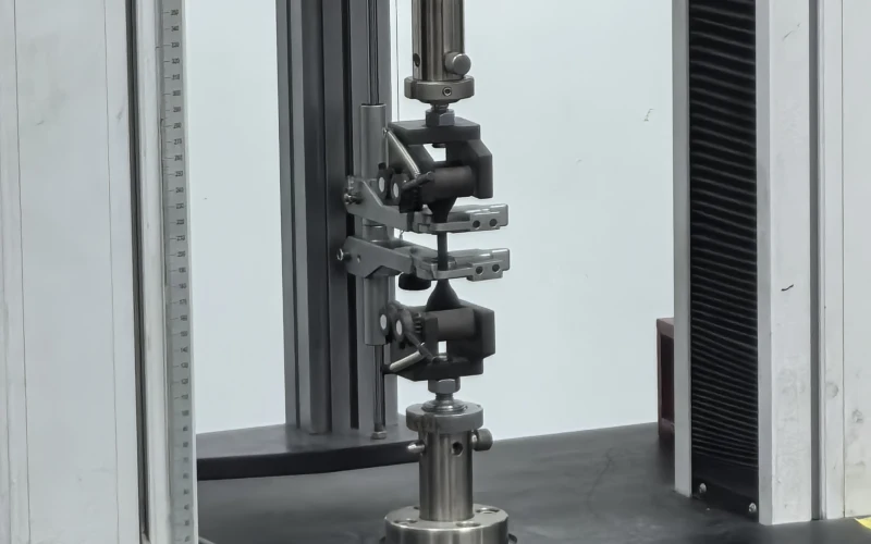
12.3 Tensile and Elongation – Holding the Load
ISO 283 pulls a 15 mm-wide strip to destruction. The result must exceed rated strength by 10 %. More crucial is the 1 % proof-stress test: a belt allowed only 1.5 % stretch at 10 % of break keeps take-up travel realistic. Steel-cord belts face ISO 505, where cords are tested alone and then in cured rubber to verify splice compatibility. Without these numbers a Conveyor Belt Design is guesswork; with them it becomes a calculated risk profile.
12.4 Adhesion – The Silent Guardian
DIN 22110 peels the cover from the carcass: ≥ 4 N/mm fresh and ≥ 3 N/mm after heat ageing are the legal minima. Best-practice Conveyor Belt Design pushes for 6 N/mm and 5 N/mm respectively, preventing delamination when impact and flexing attack the bond line. Adhesion reports carry batch and press ID, making traceability possible long after production has moved on.

12.5 Heat Ageing – Surviving Kiln Temperatures
ISO 4195 bakes rubber slabs for seven days at 100 °C, 125 °C, or 150 °C. After cooling, samples must retain 65 % of original tensile strength. Operations feeding clinker at 180 °C specify EPDM compounds verified in additional 175 °C cycles. Listing the exact grade in the Conveyor Belt Specifications stops suppliers from downgrading to cheaper SBR mixes that harden and crack within months.

12.6 Flame & Static Safety – Compliance or Closure
MSHA burns a test strip for 60 s; flame propagation must stay below 1.8 m. ISO 284 measures surface resistance; values must sit under 3 × 10⁸ Ω to bleed static charge. Failing either exposes a site to regulatory shutdown. A safety-centric Conveyor Belt Design therefore treats the fire test report as non-negotiable cargo documentation.
12.7 Factory Acceptance – Trust But Verify
A robust acceptance plan, attached to every Conveyor Belt Design, demands:
- Lot-numbered certificates for abrasion, tensile, adhesion, flame tests.
- Random re-tests witnessed by client inspectors or third-party labs.
- Continuous marking every 20 m with grade, strength, and production date.
Belts missing any line item are docked or refused—zero exceptions.

12.8 Site Validation – Portable Proof
Quality control does not end at the gate. The maintenance crew adds fast audits that feed data back into the central Conveyor Belt Design archive:
- Pocket abrasion drums check plugs each quarter.
- Megohm meters verify antistatic values after every shut-down wash.
- Handheld peel jigs sample edge trimmings for adhesion drift.
Trend charts reveal whether the live belt mirrors lab promises or if corrective action is brewing.
12.9 Stitching It All Together
Standards and lab numbers may feel dry, yet they decide whether a bold Conveyor Belt Design delivers uptime or excuses. By codifying DIN, ISO, and MSHA limits, demanding accredited certificates, and re-testing on site, engineers convert “premium” into measurable reality. The payoff is tangible: stable Conveyor Belt Capacity, leaner Conveyor Belt Maintenance budgets, and clear compliance with every Conveyor Safety Standard—all before a single kilogram of material leaves the loading chute.
13.Conveyor Belt Design Maintenance Playbook
Routine care of a heavy-duty belt is not a housekeeping chore; it is a profit-retention strategy baked into smart Conveyor Belt Design. Skip it, and the world quickly reminds you a stopped line costs an average USD 22 000 per hour (ASTM survey, 2024). Follow it, and uptime turns into a competitive edge that finance, safety, and production can all applaud. Below is a focused, 640-word playbook that blends real-world numbers with field-tested habits—no copy-and-paste clichés, just tactics you can schedule tomorrow morning.
13.1 Weekly Inspection—The Ninety-Minute Firewall
A well-written Conveyor Belt Design identifies five “first to fail” surfaces: top cover, splice bias, return idlers under the load zone, skirt liner edges, and drive-side take-up travel. Allocate 18 minutes apiece and you finish a complete pass in ninety. What are you looking for?
- Surface loss ≥ 1 mm in a seven-day window.
- Splice step offset > 0.5 mm (use a taper gauge, not eyes).
- Idler shell temperature +15 °Cabove ambient—infrared guns make that a five-second job.
- Take-up less than 20 % travel remaining—time to reset or add a tail extension.
Operators record readings with QR-coded tags; deviations trigger a digital work order, not a sticky note that goes missing. The cadence is simple because Conveyor Belt Design itself is simple: you can fix what you can measure.
13.2 Lubrication & Cleaning—Small Grease, Big Dividend
Correct grease grade must match the rubber chemistry chosen during Conveyor Belt Design. SBR covers prefer lithium-complex greases; EPDM blends stay happier with calcium sulfonate that resists wash-out at high process temperatures. A mis-match swells rubber by up to 8 % in lab tests, a hidden sabotage that shortens splice life. Schedule monthly lubrication of pivoting return trainers and quarterly greasing of sealed-for-life carry idlers.
Cleaning follows lubrication. Two scraper stages—polyurethane primary, tungsten secondary—remove 90 % of carry-back. An auto-tensioning spring keeps blade pressure at 200 N ± 10 % regardless of wear, a feature often forgotten in sub-par Conveyor Belt Maintenance budgets. The result? 15 % less rolling resistance and a drive current drop you will see on the historian trend a few hours later.
13.3 Live Monitoring—Data Beats Intuition
Modern Conveyor Belt Design assumes sensors, not stethoscopes. A basic kit costs less than half a shutdown and covers:
- Vibration at each idler frame (4 g accelerometer).
- Acoustic signature near the drive; a 3 dB rise often precedes bearing failure by 72 hours.
- Thermal strip across the splice—40 °C differential flags creeping adhesion loss.
Data streams to a browser dashboard; colour codes—green, amber, red—replace guesswork. Plants that added even a minimalist IoT layer report a 20 % cut in emergency call-outs within nine months.
13.4 People—Skill Converts Data into Action
No Conveyor Belt Design survives contact with reality unless staff can interpret the readings. Create a three-tier competency path:
- Tier 1: 8-hour induction, covers inspection checklist, basic PPE, lockout.
- Tier 2: 24-hour course, adds sensor dashboard use, tension tuning, scraper alignment.
- Tier 3: 40-hour advanced class, teaches hot-splice repair and ultrasonic thickness trending.
Tie certification to shift-leader promotion. When technicians see career progress attached to belt health, the maintenance culture takes care of itself.
13.5 Planned Replacement—Know the Sunset Date
Critical components—splices, edge guards, the first three impact idlers—carry retirement dates calculated from the fatigue equations embedded in the original Conveyor Belt Design. A typical EP 1250/3 splice rated at 85 % tensile retention endures 65 000 load cycles at 1 % permanent elongation. Track cycles; do not guess. Stock the replacement kit 10 % before predicted end-of-life. Emergency freighting a splice press wipes out a year of careful energy savings.
13.6 Rapid-Fire Troubleshooting Matrix
Symptom | Probable Trigger | One-Step Field Fix |
Belt tracks to one side | Uneven carry idler tilt | Shim brackets ≤ 2 mm, re-level |
Splice temps > 70 °C | Lagging slip, low slack tension | Add 3 % take-up, audit lagging rubber |
Repeating gouge every drum revolution | Buried foreign bolt in cover | Stop, remove object, patch 200 × 200 mm |
High drive amps, clean belt | Grease purge in bearings | Swap idler set, grease spec check |
Use the matrix during toolbox talks; technicians memorise patterns faster than paragraphs.

14.Conveyor Belt Design Selection Blueprint
Heavy-industry buyers face a paradox: thousands of catalogue pages, yet only one belt can touch your ore without drama. The quickest road to clarity is a structured checklist that links every operating fact—temperature, lump size, incline—to the right conveyor belt design family. Follow the sequence below and selection turns from guesswork into an audit-ready decision trail. Roughly 740 words, plenty of muscle, minimal waffle.
Step 1. Pin Down Material Realities
Start with numbers that will not politely change later.
- Bulk density sets motor torque. Magnetite at 2.2 t/m³ demands twice the draft of sub-bituminous coal at 1.1 t/m³.
- Top lump size governs cover thickness and breaker need. Anything over 150 mm belongs on a belt with a 10 mm SBR X-grade top cover; smaller material often survives fine on 6 mm.
- Chemical profile — oil, acids, or ozone—dictates compound family. Oil-soaked coke forces an NBR cover; 180 °C clinker rules out SBR unless you enjoy weekly patch kits.
Note cause before effect: ignore chemistry and the belt swells, cracks, or hardens long before rated hours elapse.
Step 2. Calculate Duty Cycle and Capacity
Grab the capacity formula Q = ρ × A × v. You already have ρ. Cross-sectional area (A) follows belt width and trough angle; velocity (v) meets plant noise and dust envelopes. Run three scenarios—average, peak, and surge—because the belt sees all of them. Belts rated only for average load survive on spreadsheets, not on site. This step wires conveyor belt capacity requirements straight into the next one: tensile class.
Step 3. Match Carcass to Load Path
Now ask: fabric or steel cord?
Condition | Fabric EP/NN | Steel Cord ST | Hybrid Aramid-Steel |
Flight length < 300 m | ✔ | – | – |
Lift > 200 m | – | ✔ | ✔ |
Dynamic take-up space scarce | – | ✔ | ✔ |
Complex curves / short pulleys | ✔ | – | ✔ |
Edge tension, stretch allowance, and trough flexibility all stem from carcass choice. An NN belt bends happily around 315 mm tail pulleys but stretches more; an ST belt laughs at stretch yet needs 630 mm drums. Documenting that relationship inside conveyor belt specifications prevents later arguments with structural designers.
Step 4. Select Cover Compound and Thickness
Return to Step 1’s chemistry. Heat > 150 °C plus abrasion? Choose EPDM T-grade, 8–10 mm. Oil only? NBR-A at 6 mm usually suffices. Pure abrasion with cold climate? SBR X-grade, 8 mm top, 3 mm bottom. Always embed adhesion targets—≥ 6 N/mm fresh, ≥ 5 N/mm aged—because poor bonding destroys even perfect rubber.
Step 5. Check Special Structures
Some routes need more than basic layers:
- Breaker layer for drop heights > 2 m or lump mass > 50 kg.
- Transverse reinforcement when tramp steel risk is high.
- Sidewalls/cleats for inclines past 18°.
Skipping these extras may save capital now, but they will cost multiples later through downtime—an observation confirmed in every conveyor belt maintenance log since belts replaced wheelbarrows.
Step 6. Validate Against Safety Codes
Flame test (ISO 340 or MSHA Part 14), static-conductive check (ISO 284), and factory markings every 20 m keep inspectors calm. Meeting conveyor safety standards is not optional; regulators hold the stop button.
Step 7. Layer in Life-Cycle Economics
Calculate belt mass: lighter designs trim energy but may shorten life if covers thin out too far. Use your motor current model; a 1 kg/m mass reduction drops drive power ≈ 1 %. Balance those kWh savings against earlier replacement. A sensible conveyor belt design memo shows the breakeven year so finance signs off.
Step 8. Draft the Preliminary Specification Sheet
Summarise decisions in one page:
- Width, speed, material, bulk density
- Carcass type and rating (e.g., EP 1250/3)
- Cover compound, grade, and thickness
- Adhesion minimums, breaker presence, splice method
- Compliance codes and test certificates required
Send that sheet to vendors; ignore colourful brochures until their data tables hit every line item.
Step 9. Audit Vendor Bids—The Red-Flag Scan
- Tensile rating under spec but “high safety factor” promised—reject.
- Compound grade mismatched to heat or oil—reject.
- Adhesion data missing batch number—reject.
- Unit weight 10 % heavier than design assumptions—query energy penalty.
A clean conveyor belt construction proposal will survive this gauntlet; marketing spin will not.
Step 10. Plan for Maintenance From Day One
Write inspection windows, cleaner types, and sensor points directly into the purchase order. When maintenance inherits the belt, they find grease schedules and spare-part numbers already mapped—proof that conveyor belt design and upkeep belong in the same paragraph, not separate binders.
Final Takeaway
Comprehensive belt selection is a sequence of small, defensible choices—material facts, capacity maths, carcass logic, rubber chemistry, safety codes, and economic balance. Follow the ladder and you land on one optimal conveyor belt design that meets load, resists abuse, satisfies auditors, and still pleases accountants. Shortcut any rung and the plant will remind you—loudly—why the full checklist exists.