Tip:All parameters referenced in this article come from one of our actual production projects.
1.Introduction
If you’re running a high-tension, long-distance, or heavy-load conveyor system, chances are you’re already using — or considering — an aramid conveyor belt. It’s lighter than a steel cord belt and offers better tear resistance, but there’s one condition attached: splice aramid conveyor belt has to be done right. It doesn’t matter how much tension the belt itself can carry — if the splice can’t hold, the whole belt can’t hold.
In this guide, we’ll walk through everything you need to know: why the splicing logic for aramid belts is different from other belt types, how the splice itself is engineered, what a standard conveyor belt splicing procedure looks like, how to judge splice quality once it’s done, and how to trace the root cause when something goes wrong. We’ll use the actual splice parameters from a real production run of a 3500 N/mm-rated aramid belt (DP3500-2000×1, 2000 mm width) as a working example — so what you’re reading isn’t abstract theory, but numbers that have actually been put into production.
We manufacture aramid conveyor belts. This guide is a technical and process reference, intended for your own installation team or a professional splicing contractor to work from.
If all you need is how to splice an aramid conveyor belt, skip ahead to the “Splicing Procedure” section. If you want the engineering logic behind it, read straight through.
2.Why Aramid Belts Need Finger Splicing
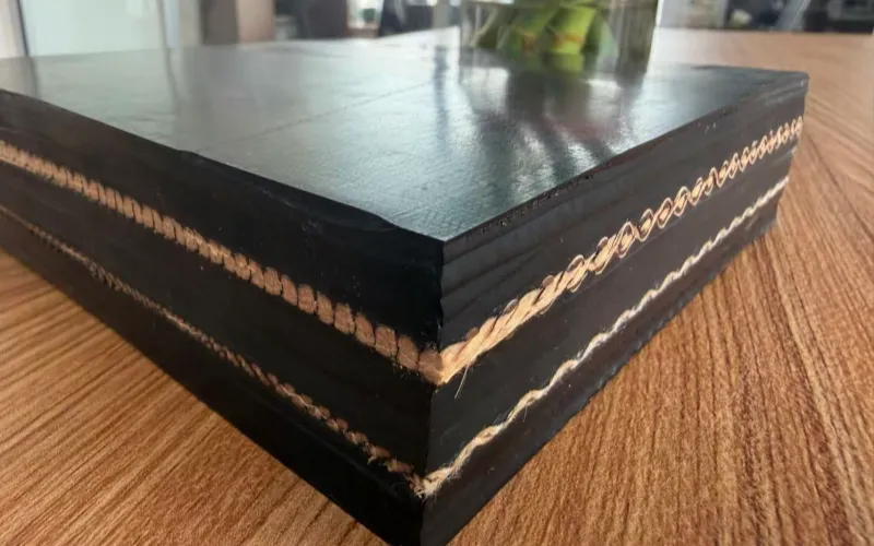
Aramid fiber has one built-in weakness: poor resistance to compression fatigue. Repeatedly bending or compressing it causes it to lose strength far faster than it would under pure tension. That’s why, when designing an aramid belt carcass, the priority is keeping the fiber under constant tension and out of compression. To achieve that, modern aramid belts are generally built with a straight warp construction — every aramid warp yarn runs in one flat plane, straight, uncrimped, and under constant tension. Weft and binder yarns sit above and below that plane to hold the warp in position, but the aramid fiber itself never experiences compression at any point.
That same requirement — keeping the warp under constant tension — is also why aramid carcasses are generally built as a single ply. Stacking multiple plies would inevitably introduce localized compression between layers, which defeats the entire point of the design.
A single-ply carcass has a direct consequence: step splicing, which relies on staggering multiple fabric plies against each other, has no room to operate on this kind of structure. Step splicing needs several plies of fabric, each skived to a different length so they stagger into a stepped profile through the belt’s thickness — and an aramid belt only has one ply, with no second or third layer to stagger against. Given the single-ply, straight-warp design that’s currently standard across the industry, the only geometry that can spread the joint‘s load without cutting straight through the load-bearing warp is the finger splice — cutting each belt end into a row of interlocking, tapered fingers, so the bonded area is stretched out and the load transfers gradually, rather than concentrating on one straight cut line.
For context: aramid’s tensile strength is around 3600 MPa and its elastic modulus around 112,000 MPa — both close to steel cord (3925 MPa and 170,000 MPa respectively) — but its specific gravity is only 1.44, less than a fifth of steel cord’s 7.85. That’s the combination that lets an aramid belt be both strong and light. But it also means low elongation and high modulus, which raises the precision required when building the splice — small errors that a polyester or nylon fabric belt might tolerate get amplified under load on an aramid belt.
3.What a Finger Splice Actually Looks Like
3.1How Finger Dimensions Are Determined
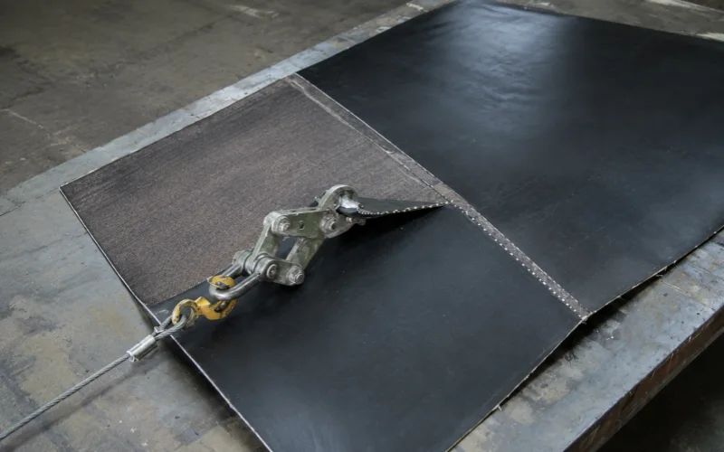
A finger splice cuts each belt end into a row of long, tapered fingers, then interlocks the two rows and bonds them together with uncured splicing rubber. The standard base width for a finger is 50 mm, chosen because most belt widths are manufactured as multiples of 50, which makes finger layout straightforward.
Finger length is derived from pull-out testing, in two steps:
Step one — a test splice is built first, using a fixed reference size of 100 mm-long, 50 mm-wide fingers on both ends, cured normally through vulcanization. Once cured, a single finger is cut from the sample and pulled on a tensile testing machine to measure the force needed to pull it out from between the two opposing half-fingers (this pull-out force is recorded as τg). This step measures the actual bonding capability of that specific material combination — the cement, the carcass, and the bonding process. The expected outcome here is that the finger pulls out rather than breaks — that’s the normal, intended result of this step, not a failure.
Step two — that pull-out force value, combined with the belt’s actual strength rating and the finger width to be used in production, is used to back-calculate the real finger length for production. A longer finger has more bonding area and therefore requires more force to pull out, so the correct finger length can be calculated proportionally: the length at which the pull-out force matches the force that finger cross-section should carry — and break at — under the target strength rating. Only at that calculated length does the splice reach the design intent of the finger breaking before it pulls out, and that outcome is ultimately confirmed through full dynamic fatigue testing.
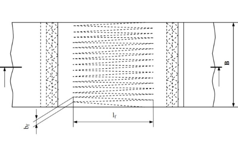
Here’s what that looks like with real numbers. For a belt rated at 3500 N/mm, the finalized production parameters are:
Belt Strength Rating (N/mm) | Finger Width b_f (mm) | Finger Length L_f (mm) | Reinforcement Length l_d (mm) | Splice Length l_v (mm) |
3500 | 90 | 4100 | 4400 | 4600 |
Note that the production finger width (90 mm) is wider than the 50 mm reference base — finger width itself scales with belt strength rating, and both the width and length need to be independently verified for each strength class. You can’t carry parameters over from one rating to another.
3.2How Force Travels Along the Finger
The force a finger carries isn’t uniform along its length — it decreases gradually from base to tip, because the cross-sectional area narrows as the taper narrows, so less force can be transmitted at the tip. This is exactly why a finger splice outperforms a straight butt joint: instead of the full tension load sitting on one line, it transfers gradually across the entire tapered length, with each cross-section along the way carrying a proportionally smaller share.
During lay-up, adjacent fingers are not butted directly against each other — a 2–3 mm gap is deliberately left between them, and that gap is filled with splicing rubber rather than left as a dry contact line. The more precisely that gap is controlled, the more evenly load is shared between adjacent fingers.
3.3 The Role of the Reinforcement Layer and Bonding Layers
The finger tips are the most vulnerable point in the entire splice — especially near a pulley, where radial force or trapped material buildup can force individual fingers apart (referred to in the industry as “pop-out”). To prevent this, an open-weave reinforcement fabric is bonded above and below the finger-jointed carcass, extending past the finger tips.
Here’s the real case again: the reinforcement layer used on the DP3500 splice is NN200-1980 canvas, factory-precoated with 0.8 mm of cement on one face and 3.0 mm on the other — the more heavily coated face is laid against the carcass — at a calendared thickness of 4.5 mm per layer, applied both above and below. This reinforcement fabric’s own tensile strength plays no role in the splice’s load calculation — its only function is preventing the finger tips from separating, which is why an open weave is specifically chosen to maximize adhesion rather than fiber strength.
3.4 Restoring the Cover Rubber
Once the carcass splice and reinforcement layers are laid up, the top and bottom cover rubber needs to be fully restored so the splice area matches the rest of the belt in wear resistance, impact resistance, and sealing performance.
4.How an Aramid Belt Splice Differs From Other Belt Splicing Methods
The finger splice used on aramid belts, the step splice used on EP/NN multi-ply fabric belts, and the splice used on steel cord belts are three entirely different mechanical approaches — they’re easy to conflate, so it’s worth separating them clearly.
① EP/NN multi-ply fabric belts: the true “step” splice. These belts have a carcass built from several stacked plies of fabric. To splice them, each ply is skived to a different length, staggered from top to bottom, so that when the two belt ends come together, each ply’s cut end overlaps with the corresponding ply from the other end. In cross-section, this produces a genuine staircase profile — which is where the term “step splice” actually comes from: a stepped cross-section running through the thickness of the belt. This method requires multiple fabric plies to work at all.
② Steel cord belts: a staggered lap splice, not a step splice. A steel cord belt’s carcass isn’t layered fabric — it’s a single plane of parallel steel cords laid side by side. Cords can’t be skived into a thickness-wise staircase the way fabric plies can. Instead, the rubber is stripped from each cord end and the cords from both belt ends are lapped together — but the lap starting point for each cord is deliberately staggered relative to its neighbors, so that at any given cross-section along the splice, only some cords are in their transition zone while the rest remain fully continuous. Viewed from above, this staggered layout does have a somewhat “stepped” visual pattern, but mechanically it has nothing to do with the true through-thickness step splice used on EP belts — the accurate term is a staggered cord lap splice.
③ Aramid belts: single-ply, so neither method applies — only a finger splice works. An aramid belt’s carcass is a single-ply, straight-warp structure — it has neither the multiple plies needed for a step splice nor the side-by-side cord layout of a steel cord belt. The only way to spread the load across the joint without cutting straight through the warp is to cut the entire single-ply carcass into interlocking fingers and bond it as one continuous sheet. This is the fundamental difference between an aramid belt finger splice and the other two methods.
Test data backs up the reliability of this approach. Under the standard Hannover University dynamic fatigue test — a spliced endless belt run on a test rig where tension ramps from 10% to 100% of the fatigue load on a 50-second cycle, with a requirement of 10,000 cycles without failure — steel cord belt splices typically achieve around 50% dynamic splice efficiency. High-strength woven fabric belt finger splices, under the same test conditions, have historically returned just over 30%.
Aramid belt splices built on this finger-splice logic have matched that: three tested samples all reached 30% dynamic fatigue strength, on par with comparable woven fabric belts. In a separate reverse-bending test — the belt run around four pulleys, with tension starting at 12.5% of breaking strength and increasing 5% every 125,000 cycles until failure — the splices held up to 27–32% of the belt’s full breaking strength before failing, and post-test tensile measurement showed less than a 5% reduction in carcass strength.
That confirms the straight-warp aramid carcass doesn’t lose fatigue life from the splicing and high-load cycling process — historically one of the open questions about whether aramid belting could hold up to long-term service, and one the data now answers.
5.Mechanical Fasteners: Very Limited Fit for Aramid Belts
Mechanical fasteners are a common temporary repair method on some belt types, but on aramid belts specifically, there are a few real limitations worth spelling out:
Steel plate fasteners are technically possible, but their practical use is also very limited. Aramid belts are often built to match steel cord belt strength ratings, which means the finished belt is typically thicker than a comparable steel cord belt. Unless the fastener’s bolts are long enough to match that thickness, proper installation and a secure clamp become difficult.
Overall, mechanical fasteners aren’t a standard solution for aramid belts — they’re more of a theoretical option that sees very little real-world use. For high-tension applications, hot vulcanized splice remains the only method that reliably holds up.
6.Core Hot Vulcanized Splice for Aramid Conveyor Belt Procedure
Below is the standard process for this splicing method, presented as a technical reference for your installation team or your contracted splicing provider to follow. Each step includes the key actions, parameters, and points to watch.
Step 1: Site and Material Preparation
The work area needs to be clean, dry, and out of direct sunlight, with no wind or airborne dust during the operation — wind affects cement flash-off time, and dust that gets into the bond line will compromise adhesion. Ambient temperature should not fall below 15°C, since low temperatures slow cement curing and weaken bond strength; high-humidity conditions should also be avoided where possible, and the work area should be sheltered if rain or snow is a factor.
Materials needed: splicing cement (mixed from 120# rubber solvent and core compound at a 5:1 ratio, or a pre-mixed proprietary cement — shelf life is typically around 6 months, stored cool, dry, shaded, and away from ignition sources), a cleaning solvent (120# rubber solvent or a dedicated splice cleaner), and release material (non-woven fabric or high-temperature release paper, placed between the splice and the vulcanizing press platen).
Step 2: Marking the Centerline and Determining Total Splice Length
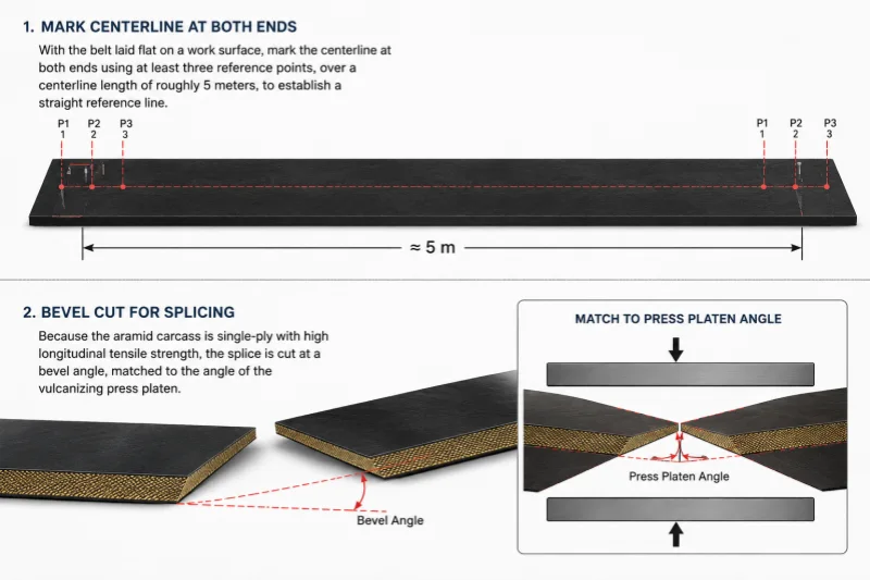
With the belt laid flat on a work surface, mark the centerline at both ends using at least three reference points, over a centerline length of roughly 5 meters, to establish a straight reference line. Because the aramid carcass is single-ply with high longitudinal tensile strength, the splice is cut at a bevel angle, matched to the angle of the vulcanizing press platen.
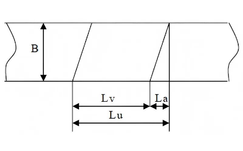
Total splice length is calculated as the splice length l_v (set by belt strength rating — 4600 mm for a 3500 N/mm belt) plus the bevel allowance (0.3 × belt width B). For a 2000 mm-wide belt, that’s 0.3 × 2000 = 600 mm, giving a total working splice length of 5200 mm. Each end’s sealing width runs about 150 mm (roughly a 100 mm finger-tip-to-root offset plus a 50 mm bevel).

Step 3: Skiving the Cover Rubber
With the belt on the work table or the press platen, working face up, cut a 45° bevel along the sealing line (being careful not to damage the carcass fabric), then skive the top cover rubber back from the sealing line along the belt’s length — the strip length equals finger length plus 150 mm (4100 + 150 = 4250 mm for the 3500 rating). Flip the belt and skive the underside cover the same way, offsetting the starting point by 100 mm from the top-side start, with the same strip length.
Once both sides are skived, buff the exposed area and sealing edges with an angle grinder (a wire-brush wheel is preferred), leaving about 1 mm of core rubber without damaging the carcass fabric. Feather the cover rubber at the sealing line out an additional 30 mm or so for a smoother transition. Repeat the same process on the other belt end.

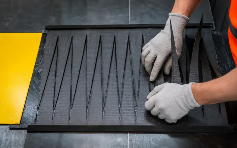
Step 4: Marking and Cutting the Fingers
Mark the finger pattern on the buffed carcass surface using a straightedge or a template. Start from the centerline, and pay attention to the belt’s running direction — on the leading end (in the direction of travel), the two outermost fingers should sit at the belt edges, and the finger pattern on the opposite end must match it exactly. Working out from the centerline, both sides’ finger widths need to stay above 0.5 × the standard finger width (for a 90 mm standard, neither side should go below 45 mm). Total splice length matches the value calculated in Step 2. Cut the fingers along the marked lines.
Step 5: Cementing, Reinforcement Lay-up, and Finger Assembly
Lay release material on the press platen, position the belt with the centerlines aligned and secure it, keeping the two outermost fingers on the leading end positioned at the outer edge.
Clean both splice ends’ finger faces and sealing edges with solvent to remove dust and grinding residue, then apply cement once dry — two coats, with the first coat fully flashed off before the second is applied, and lay-up beginning once the second coat is roughly 80% dry.
Cut the cover rubber (extending about 50 mm past the belt width on each side, matched to the splice angle), and lay reinforcement fabric on top (narrower than the belt by 30–50 mm on each side, set back 20–30 mm from each sealing edge), rolling it to remove trapped air. Place this cemented cover-and-reinforcement base on the press platen and check that the sealing surfaces are evenly coated with rubber, extending about 50 mm past the belt width.
Apply cement to the reinforcement layer, and once dry, interlock the fingers in sequence, holding a 2–3 mm gap between adjacent fingers, filled with rubber. Once the row is fully interlocked, apply another coat of cement, and once dry, lay a second reinforcement layer over the top, again rolling to remove air. Build up edge rubber on both sides to match carcass thickness, apply and press down the cover rubber, and trim both edges flush with the belt body. Finish by placing release material over the splice, fitting end dams, and securing with tie rods.
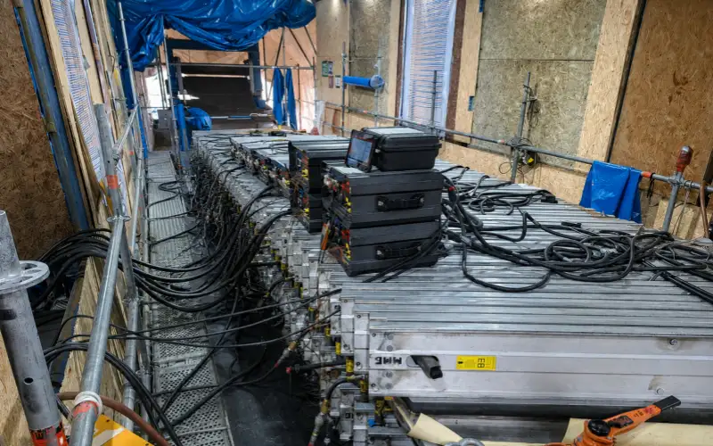
Step 6: Hot Vulcanization
Pressurize the platens to 0.8 MPa while heating begins. Once temperature reaches 100°C, release the pressure and re-apply to 1.5 ± 0.2 MPa. Start the cure timer once temperature reaches approximately 145°C, and hold for a cure time of 65 minutes.
Step 7: Cooling and Finishing
Release pressure only once the splice has cooled below 70°C, then open the press. Trim and buff any excess rubber at the seal lines and edges flush, and check the centerline and both edges for straightness using a taut reference line. Correct any deviation found, and complete the process with a full record of the operation.
7.Key Factors That Determine Splice Strength
How strong a finished splice turns out depends on the following variables:
Whether finger length matches the belt’s strength rating — each strength class requires its own verified finger length; parameters can’t be carried over between ratings.
Whether the bonding layers are properly built — the cement coats between carcass, reinforcement, and cover rubber are what turn a mechanically interlocked finger pattern into one continuous load-carrying structure. A missed coat, a coat applied too wet, or contamination on a bonding surface directly weakens the splice.
Whether cure conditions are fully met — temperature, pressure, and time all need to hit their targets simultaneously; falling short on any one of them leaves the splice looking finished while remaining under-cured.
Whether workmanship stays consistent — manual steps like finger spacing and buffing depth, if uneven, create local weak points in the splice, and a local weak point often fails sooner than a joint that was uniformly, conservatively built.
8.Common Aramid Conveyor Belt Splice Problems and Root Causes
Splice opening — usually traces to insufficient cement coverage, incomplete vulcanization (check against the Step 6 parameters), or contamination not fully removed during the Step 5 cleaning pass.
Edge cracking — typically linked to edge rubber that wasn’t built up to match carcass thickness, or long-term belt tracking issues that concentrate stress on one side.
Air bubbles — a result of insufficient air removal during rolling, or cement layers that weren’t fully dry before the next layer was applied.
Misalignment — traces back to Step 2, either an inaccurate centerline or finger patterns on the two ends that don’t fully correspond.
Early splice failure — usually not one single cause, but a combination: finger length not matched to the belt’s actual tension, conservative cure parameters, and pulley or tension design putting more cyclic stress on the splice than it was built to handle.
9.Tools & Equipment Checklist for Aramid Belt Hot Vulcanized Splicing
| No. | Item | Unit | Qty |
|---|
| 1 | Clamping plates | pair | 2 |
| 2 | 5 m steel tape measure | pc | 1 |
| 3 | Angle ruler | pc | 1 |
| 3 | Ordinary 2–3 mm steel plate (sized to match original belt; plate thickness set 1–1.5 mm thinner than original belt, per belt width/length) | pc | 1 |
| 4 | White wax marking pencil | pc | 1 |
| 5 | Chalk line marker | pc | 1 |
| 6 | Marker pen | pc | 2 |
| 7 | Utility knife | pc | 4 |
| 8 | Blades | box | 3 |
| 9 | Screwdriver | pc | 1 |
| 10 | Scissors | pc | 1 |
| 11 | Wire/cable cutter | pc | 2 |
| 12 | Angle grinder with wire wheel | unit | 1 |
| 13 | Skiving machine (manual skiving also acceptable) | unit | 1 |
| 14 | Rubber mallet (5 lb) | pc | 1 |
| 15 | Putty/spreading knife | pc | 4 |
| 16 | Hair dryer / heat gun | pc | 1 |
| 17 | Long straightedge ruler | pc | 1 |
| 18 | Brush | pc | 2 |
| 13 | Plastic basin | pc | 2 |
| 14 | Wire brush head (for angle grinder) | pc | 2 |
| 15 | Buffing/roughing tool | pc | 2 |
| 16 | Mercury thermometer, 0–200°C | pc | 10 |
| 17 | White cotton cloth or lint-free towel | m / pc | 1 or 4 |
| 18 | Safety helmet | pc | 4 |
| 19 | Welded 3 mm steel plate work platform (length/width per site; height = lower beam + water plate + lower heating plate thickness) | unit | 2 |
| 20 | Explosion-proof vulcanizing press (underground) or standard press (above ground) — quantity depends on splice length and specification. Each press requires: 10 I-beam crossbars, 10 tie rods, 1 water hose, 1 hydraulic pump, 2 wrenches, 1 primary power feed cable, 2 secondary power feed cables for heating plates, 1 power control box, upper/lower heating plates, water pressure plate, and electric pump hose matched to equipment requirements | set | 1 |
| 21 | Manual/electric chain hoist and clamps | pair | 2 |
| 22 | 120# rubber solvent / dedicated splice cleaner | L | 5 |
| 23 | Splicing rubber compound | set | as required |
| 24 | Splicing cement | set | as required |
| 25 | Release paper or PTFE (Teflon) cloth to separate heating plates from belt during vulcanization | m | as required |
| 26 | Timber boards, supports, and nails for platform construction | / | as required |
| 27 | Power and water supply | / | sufficient for equipment operation |
10.Conclusion
A splice is never a minor detail on an aramid conveyor belt — it’s the point where carcass design, bonding process, and installation quality all come together, and it’s usually what determines how long the belt actually lasts. If you need matched splicing parameters for a specific belt specification, send us your belt width, strength rating, cover thickness, and conveyor parameters, and we can help confirm the right finger dimensions and vulcanization parameters as a reference.
11.FAQ
What splicing method is best for an aramid conveyor belt?
A hot vulcanized finger splice. An aramid belt’s single-ply, straight-warp carcass means step splicing — which depends on staggering multiple fabric plies — has no room to operate. Finger splicing is currently the method that spreads the joint’s load without cutting through the load-bearing fiber.
Can an aramid conveyor belt use mechanical fasteners?
In theory, as a temporary emergency measure — but real-world use is very limited. Plastic fasteners aren’t strong enough and tend to crack, and steel plate fasteners are constrained by the aramid belt’s typically greater thickness, making installation difficult unless bolt length is properly matched. A hot vulcanized splice remains the more reliable option for high-tension use.
How strong can an aramid belt splice be?
It depends on whether finger length matches the belt’s strength rating, whether the bonding layers are properly built, and whether cure parameters are fully executed. A correctly built finger splice can reach over 30% dynamic fatigue efficiency under Hannover University standard testing — on par with comparable high-strength woven fabric belts.
Why does an aramid belt splice fail? Most cases trace back to insufficient cement coverage, incomplete vulcanization, contamination left in the bond line during lay-up, or finger dimensions that don’t match the belt’s actual strength rating.
How is an aramid belt splice different from an EP or steel cord belt splice?
EP multi-ply fabric belts use a true step splice, where staggered fabric plies form a stepped cross-section. Steel cord belts use a staggered lap splice, where cord lap positions are offset rather than layered into steps. Aramid belts, with their single-ply carcass, can’t use either method — only a finger splice works.