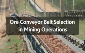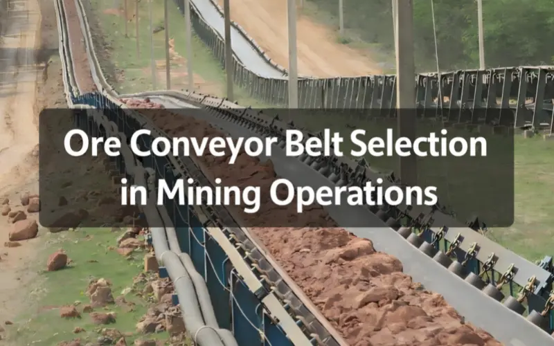
Ore conveyor belt selection in mining cannot be judged by specifications alone. This article explains how ore behavior, transfer conditions, and operating assumptions shape impact zones, wear patterns, and long-term belt performance in real operations.
1.Why Ore Conveyor Belt Performance Can Vary Significantly in Mining Operations
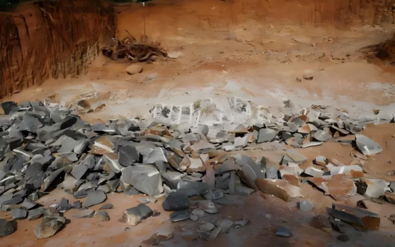
Two EP630/4-ply ore conveyor belts, identical specifications, same cover rubber grade. Site A in Western Australia: belt replaced after six months. Site B in Queensland: same belt, still running after 18 months.
Same supplier. Same ore type on the spec sheet. Completely different service life.
This isn’t a supplier quality issue. It’s not about “choosing the wrong belt.” The problem runs deeper — ore behavior in actual conveying conditions is far less predictable than most initial assessments assume.
In standard bulk material applications, materials like coal or grain flow relatively consistently. An ore conveyor belt faces something different entirely. Iron ore doesn’t just sit on the belt — it rolls, slides, repositions itself with every vibration and grade change. A 15-degree shift in discharge angle at a transfer point can move the primary impact zone by 300mm, concentrating wear in completely different areas of the cover rubber.
Particle size distribution plays a larger role than many projects account for. A batch dominated by 80-120mm lumps creates different contact dynamics than one with mixed fines and occasional 200mm+ rocks. The belt doesn’t “see” average particle size — it responds to every individual impact, every edge load, every localized pressure point.
Transfer point design compounds this. Drop height, chute angle, belt speed at loading — each variable changes how ore contacts the belt surface. In one copper mine project, identical ore conveyor belts showed 40% service life variation between two parallel lines. The difference? One transfer chute had a 12-degree steeper angle. That’s it.
This is why ore conveying remains one of the more challenging applications in bulk handling systems. Performance variations in ore conveyor belts typically stem from the interaction between ore physical properties, transfer conditions, and belt structure — not from any single factor in isolation.
Most failures trace back to assumptions. Assumptions about how ore will behave. Assumptions about impact patterns. Assumptions that working conditions will match design parameters.
The ore doesn’t care about assumptions. It moves how physics dictates, not how drawings predict.
2.Understanding Ore Characteristics for Mining Belt Selection
In ore conveyor belt systems, selection discussions often begin with the belt itself. However, without considering the ore and its operating conditions, how can we truly address the issue? Just as with ore conveyor belts, the ore comes first, then the conveyor belt. The wear locations, impact concentration zones, and fatigue accumulation patterns observed during belt operation are directly determined by the physical behavior of the ore during conveying.
During project initiation, ore specifications typically appear in technical documents as density, maximum lump size, and throughput. While these data support foundational calculations, they struggle to capture the ore’s actual state on the belt. During operation, ore continuously rolls, slides, and flips due to speed variations, slope adjustments, and system vibrations, causing constant changes in contact points. The cover rubber endures not a stable load but a prolonged environment of repeatedly superimposed localized stresses.
This characteristic is particularly pronounced in iron ore conveyor belt applications. Iron ore’s high density and prominent edges make it prone to sustained edge contact during operation. Wear often concentrates in fixed zones with high repeatability. Even when overall throughput remains stable, localized wear rates can significantly exceed expectations, ultimately dictating the conveyor belt’s lifespan.
In actual mining projects, distinct differences in ore behavior during conveying are readily apparent, directly altering the location of impact zones and wear patterns:
- Iron ore conveyor belts:High-density ore with sharp edges causes simultaneous abrasion and impact, subjecting cover rubber to prolonged high-frequency localized loading.
- Copper ore: Irregular particle shapes lead to concentrated impacts at transfer points. The impact zone is smaller but exhibits higher single-point impact intensity.
- Bauxite ore:Bauxite ore’s surface characteristics lead to more frequent adhesion and surface peeling, with shear forces exerting a more pronounced effect on the cover rubber.
- Gold ore:Gold ore projects commonly involve a wide particle size range, with fine material and occasional large rocks coexisting, resulting in frequent localized high-pressure points during operation.
Particle size distribution plays a critical role in these processes. Materials predominantly in the 80–120 mm range exhibit relatively continuous contact behavior. When small quantities of oversized rock exceeding 200 mm enter the system, the impact pattern changes rapidly. The conveyor belt responds to each individual impact and edge load. While these differences may not manifest immediately, they accumulate over long-term operation, ultimately reflecting in wear patterns and conveyor belt surface damage.
In mining projects, ore characteristics typically require independent evaluation as distinct inputs. Particle size distribution, shape, hardness, and density collectively determine the actual stress conditions experienced by ore conveyor belts within the system. If this assessment layer is built upon idealized assumptions, a gap will gradually emerge between subsequent designs and actual field performance.
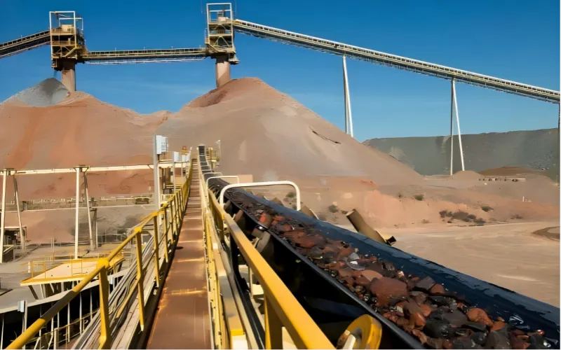
3.Typical Operating Conditions in Heavy-Duty Ore Conveying
In the actual operation of ore conveyor belts, wear, impact, and fatigue are not evenly distributed. Problems often concentrate at a few critical locations. Once these areas enter a state of continuous heavy loading, they will persistently dominate the conveyor belt’s operational performance.
3.1 Transfer Points
Transfer points are typically the first areas to exhibit problems. Here, ore undergoes directional changes and velocity reorganization, with impact and sliding occurring simultaneously. Drop height, chute angle, and belt speed combine at this point to determine the initial contact pattern between ore and belt.
Once an impact zone forms, its location decisively influences wear behavior. When ore repeatedly strikes the same area at similar angles of incidence, the cover rubber endures sustained, repetitive impacts and micro-shearing. Wear shifts from dispersed to localized accumulation, significantly increasing energy input per unit area.
When the impact zone shifts due to changes in drop angle or speed, the wear pattern evolves. Minor indentations formed during initial displacement subsequently guide the landing points and rolling paths of subsequent ore, concentrating more material at the same location. The impact zone gradually becomes “fixed” during operation, with the same area repeatedly subjected to concentrated loads, resulting in wear rates significantly higher than in other system areas. These changes do not result from sudden alterations in the ore itself, but rather from amplified contact patterns.
3.2 Drop Height and Loading Pattern
Drop height and discharge method exert a pronounced amplifying effect on ore conveyor belts. Under high-drop discharge conditions, ore experiences transient high stress upon initial belt contact, causing the cover rubber to enter an impact-dominated state first.
Different chute designs alter the ore’s orientation and contact sequence upon belt impact. The same ore exhibits markedly different impact patterns under varying discharge trajectories. In some cases, surface wear may appear minimal while internal fatigue accumulates—a condition difficult to detect visually during early stages.
3.3 Continuous Heavy-Duty Operation
Continuous heavy-duty operation is the norm in ore conveying. Systems endure prolonged high-load conditions with limited downtime windows, where any localized anomaly rapidly escalates.
As operating hours accumulate, material fatigue progressively manifests, making the stability of cover rubber and carcass critical. Issues in such conditions typically emerge as accelerated wear and diminished operational stability rather than sudden structural failure.
3.4 High-Risk Feeding Scenarios and Impact Control
Risks are particularly concentrated at the interface between the primary crusher and the conveyor. Freshly crushed ore exhibits a wide particle size distribution with a high proportion of large chunks, making the impact pattern unstable. The same applies to discharge from surge bins, where material flow is markedly discontinuous and instantaneous load fluctuations occur frequently. When high-speed belts handle large ore pieces, localized high-pressure points are more likely to form, often leading to simultaneous increases in wear and impact.
In such high-risk discharge conditions, the feeding arrangement often impacts the ore conveyor belt more directly than the belt parameters themselves. A common and effective engineering practice involves installing a rock box or an impact chute with a dead bed at the discharge point. Before entering the conveyor belt, the ore first collides with the chute’s inner walls, forming a cushioning layer that dissipates kinetic energy within the equipment.
Within this structure, most material slides down the chute’s inclined wall onto the belt surface, converting impact into sliding contact. The instantaneous impact on the conveyor belt is significantly reduced, making it easier to control the impact zone within the designed location. Consequently, the wear pattern of the cover rubber becomes more predictable. In such operating conditions, managing impact through feeding design is often more effective than simply increasing belt strength.

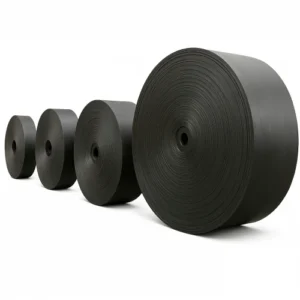
4.Ore Conveyor Belt Structural Components Explained
This section focuses solely on structural explanations without discussing correctness or drawing selection conclusions. Its purpose is to clearly break down the key structural elements of ore conveyor belts, providing a clear basis for your engineering judgments.
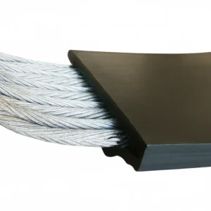
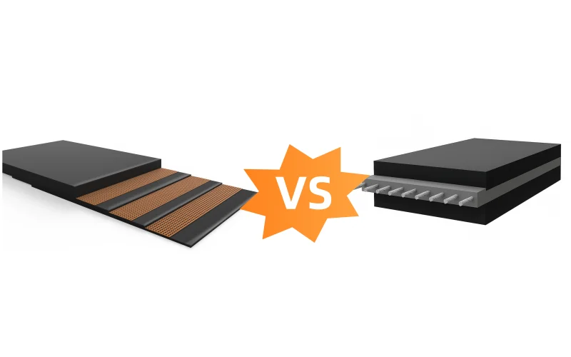
4.1 Carcass Design: EP vs Steel Cord in Ore Applications
The carcass determines how the conveyor belt withstands tension, responds to impact, and accumulates elongation during long-term operation. In ore conveying, common structural choices center on EP and steel cord types.
EP carcass consists of polyester and nylon fabrics, offering higher structural flexibility and greater ease in installation and maintenance. For medium-load ore conveying systems over short to medium distances, EP structures provide sufficient strength while offering some impact cushioning capability.
Steel cord, characterized by high longitudinal strength and low elongation, is suited for long-distance, high-tension conveying systems and is virtually synonymous with heavy-duty applications. In such structures, the belt maintains controllable behavior during starts, stops, and load fluctuations. This requires high precision in installation, joint quality, and operational alignment—direct consequences of its structural characteristics.
4.2 Top and Bottom Cover Rubber Functions
Cover rubber determines the direct contact behavior between ore and belt, with its engineering role often manifesting earlier than the carcass.
The top cover directly faces ore, enduring abrasion, impact, and cutting forces. Its performance depends on compound design, thickness, and response to tear and impact stresses. In ore conveying, top cover wear patterns typically exhibit distinct regional characteristics, closely correlated with the impact zone and material contact path.
The bottom cover interacts with drums and rollers, determining operational stability and system friction conditions. In high-load ore conveying systems, the bottom cover’s wear resistance and fatigue endurance directly impact drum lining lifespan, slip risk, and system energy consumption. Although not in direct contact with ore, its engineering significance remains substantial.
4.3 Cover Thickness and Wear Life
Cover thickness is one of the most easily quantified yet frequently misunderstood parameters in structural design. Under ore conveying conditions, wear progression is non-linear. Increasing thickness delays wear-through time but has limited effect on microcrack propagation induced by impact.
When impact dominates wear behavior, cover rubber failure typically originates internally. Microcracks progressively propagate under repeated impacts, eventually manifesting as accelerated surface wear or localized delamination. In such cases, simply increasing cover thickness does not proportionally extend service life.
Therefore, in ore conveyor belt structural design, cover thickness must be evaluated in conjunction with compound characteristics, impact patterns, and feeding arrangements—not as an isolated parameter subject to independent scaling.
5.How Ore Conveyor Belt Selection Is Typically Approached in Engineering Practice
In the process of evaluating ore conveyor belt selection, the approach typically progresses step-by-step around ore behavior and system operating conditions. The goal is to identify uncertainties as early as possible rather than passively accepting outcomes during operation. I often advise our clients to consider conveyor belt technical parameters based on the most extreme scenarios within current operating conditions.
5.1 Review Ore Characteristics and Size Distribution
Engineering assessments typically begin by examining the ore itself. Focus centers on particle size distribution, lump content, shape characteristics, and stability during operation. Field data often holds greater significance than design averages, as ore conveyor belts respond to every impact and edge load. A small number of large ore particles at the tail end of the distribution frequently dictate actual wear behavior.
5.2 Assess Impact Severity and Transfer Conditions
Attention then shifts to transfer conditions. Drop height, chute angle, belt speed, and feed symmetry directly determine the location and configuration of the impact zone. Engineers typically assess at this stage whether impacts are manageable or indicate high-risk feeding scenarios. This determination significantly influences subsequent structural selection.
5.3 Define Carcass Type Based on System Requirements
Only after ore behavior and impact conditions are clarified is carcass type discussed. Evaluation focuses on conveying distance, system tension levels, start-up and braking conditions, and elongation control requirements. EP and steel cord structures are compared within specific system contexts at this stage, rather than solely based on nominal strength ratings.
5.4 Specify Cover Rubber for Abrasion, Tear, and Impact Resistance
Cover rubber evaluation typically follows immediately after carcass selection. The top cover must match the ore’s abrasion and cutting characteristics while accounting for whether impact patterns are concentrated. The bottom cover is confirmed based on operational stability, drum contact conditions, and long-term fatigue performance. Cover thickness, compound type, and anticipated wear patterns are generally discussed holistically at this stage.
5.5 Confirm Splice Design Compatibility
In many ore projects, the operating conditions of splices differ from those of the main belt body. Therefore, during the selection process, the splice design is typically reviewed separately. The joint structure, vulcanization method, and their adaptability under actual tension and impact conditions directly impact system maintainability and operational continuity.
In engineering practice, this evaluation process does not prioritize “quick answers.” Instead, it progressively narrows uncertainties to align the ore conveyor belt’s structural design with actual operating conditions. The value of this approach is often fully realized only after the system enters long-term operation.
6.Key Considerations That Influence Ore Conveyor Belt Performance
Ore conveyor belt performance is never determined by a single parameter. Many customers submit inquiries providing only the tensile strength of either the EP or ST layer. Relying solely on this parameter makes an accurate quotation impossible. Performance variations typically stem from the combined effects of multiple factors, whose relative importance varies across different projects and manifests differently in each application.
6.1 Tensile Strength in the Overall Design Context
Tensile strength serves a defined purpose within system design, yet its scope is relatively limited. Rated strength primarily ensures the belt possesses sufficient safety margin under tension conditions, which is particularly critical for long-distance, heavy-load systems. However, in many ore projects, operational issues do not arise under extreme tension conditions but rather during localized impact, concentrated abrasion, and cumulative fatigue phases.
When system tension is properly controlled, merely increasing strength grades does not alter the location of impact zones nor reduce the contact energy between ore and cover rubber. In such cases, strength parameters primarily function as “system constraints” rather than the dominant factor determining service life.
6.2 Cover Rubber Influence on Actual Lifespan
The impact of cover rubber on the actual lifespan of ore conveyor belts is often perceived earlier than that of the carcass. Wear, cutting, and impact first act upon the cover rubber, whose failure patterns directly reflect the ore’s contact characteristics.
Under conditions of concentrated impact, cover rubber performance depends not only on abrasion resistance but also on tear resistance, rebound properties, and response to repeated impacts. When wear patterns become localized in specific areas, even with overall wear remaining low, the affected cover rubber may prematurely enter a failure stage.
6.3 Balance Between Standardized Parameters and Site Conditions
Design phases often rely on standardized parameters for selection, which is necessary for engineering purposes. However, field conditions rarely perfectly match these assumptions. Tail-end variations in particle size distribution, uneven material loading, and minor geometric differences at transfer points can all gradually amplify during operation. This is why I increasingly recommend clients consider extreme scenarios.
In ore conveyor belt applications, such deviations do not signify design flaws but are natural outcomes of system complexity. The engineering focus lies in determining which parameters should remain standardized and which factors require adjustment for site-specific extreme conditions. The choice of this balance point across different projects directly impacts conveyor belt operational stability.
6.4 Interaction Between Factors Rather Than Isolated Effects
Abrasion, impact, and fatigue rarely occur in isolation. High-impact zones typically accelerate abrasion, tension fluctuations affect splice integrity, and variations in feeding arrangements alter stress distribution on the cover rubber. These factors interact, giving ore conveyor belt performance distinct systemic characteristics.
I firmly believe that incorporating safety margins into conveyor belt design not only prevents sudden shutdowns but also serves as an effective method for extending the lifespan of individual belts.
7.Conclusion: Ore Conveyor Belt Selection in Mining Practice
Performance variations in ore conveyor belts stem from differences in ore behavior during actual conveyance, rather than discrepancies in nominal specifications. Particle size distribution, lump ore proportion, and ore morphology determine the formation location of the impact zone and whether wear will be continuously amplified.
During operation, transfer points, drop height, and continuous heavy-load conditions dictate the actual stress patterns on the conveyor belt. Once the impact zone is fixed in the field, the wear path repeats continuously over operating time, ultimately dictating belt lifespan.
Structurally, the carcass primarily constrains system tension, while the cover rubber directly bears ore forces. Strength ratings address system safety margins, whereas wear, cutting, and impact are more determined by cover rubber properties and contact patterns. Isolated increases in strength or thickness cannot alter the interaction mode between ore and belt.
The effective selection path in engineering practice remains consistent:
Understand ore behavior, confirm operating conditions, determine structural design, and finally verify strength and joints.
When this logical sequence is disrupted, risks will only manifest during operation.
8.Frequently Asked Questions|Most Commonly Discussed Issues in Ore Conveyor Belt Projects
1.After discharge from the primary crusher, localized deep-pit wear occurs. Under these operating conditions, what should be prioritized for adjustment on the ore conveyor belt?
This wear pattern typically indicates the impact zone is confined to an extremely small area, rather than simply insufficient wear capacity.
The primary engineering check should focus not on the conveyor belt structure, but on the discharge method at the transfer point:
- Is there free-falling ore striking the belt directly?
- Is the discharge unevenly loaded?
- Does the chute angle cause ore to enter the belt in a projectile manner?
A more effective solution is typically:
Using a rock box or dead bed chute to first contact the ore with the equipment’s inner walls, then slide it along an inclined surface onto the belt. Only after impact is controlled does upgrading the cover rubber or structure become meaningful.
2.In iron ore conveyor belt projects, what are common reasons for significantly shortened service life despite meeting DIN wear standards?
This issue usually stems not from insufficient cover rubber durability, but from localized, amplified wear.
In iron ore applications, high density combined with sharp edges often creates persistent edge contact. Once loading becomes uneven or the impact zone shifts, wear accumulates repeatedly along fixed paths. Even with stable overall throughput, localized wear rates can significantly exceed expectations.
Engineering should prioritize verifying:
Actual material drop points, loading alignment status, and whether impacts persistently concentrate in the same area—rather than simply “brute-forcing” solutions by increasing cover thickness.
3.For two parallel conveyor lines using identical ore conveyor belt models and batches, yet exhibiting over 30% lifespan disparity, what should be compared first?
The top priority is not belt parameters, but how ore enters the belt.
In actual projects, the variables most commonly driving lifespan disparities include:
- Slight variations in chute angle
- Differences in drop height
- Belt speed variations in the loading zone
These factors directly alter the impact pattern, causing the impact zone to become fixed at different locations. Even with identical ore conveyor belts, differing contact methods will rapidly diverge wear patterns and lifespans.
4.When surge bin discharge is intermittent, causing operational issues like belt drift, slippage, and frequent tension adjustments, where should the focus lie during belt selection?
Such symptoms typically indicate system fluctuations have propagated to the belt. The root cause lies not in the strength of the ore conveyor belt, but in operational stability.
Engineering considerations should instead focus on:
- Elongation control capability of the carcass (EP elongation management or low-elongation steel cord properties)
- Adaptability of the bottom cover to varying contact conditions with drums and rollers
- Reliability of splices under frequent tension fluctuations
In such conditions, merely increasing tensile strength rarely improves operational stability and may instead mask underlying systemic instability.
5.Where does the problem typically lie when an ore conveyor belt exhibits rapid wear only after initial normal operation?
This scenario is highly typical in ore conveyor belt projects and is often mistakenly attributed to “material quality issues.”
Normal early operation confirms the belt’s foundational strength and initial structural integrity.
Sudden accelerated wear later indicates that impact and abrasion pathways have progressively stabilized during operation.
Common triggers include:
- Minor shifts in the impact zone during operation, self-reinforcing over time
- Altered material trajectory due to chute liner wear
- Changes in particle size distribution, increasing large ore particle frequency
These shifts won’t immediately show in operational data but continuously stress the same cover rubber area until wear rates become uncontrollable.
A more effective engineering approach is to revisit the transfer point and feeding conditions to reconfirm the actual ore impact location and contact pattern, rather than directly replacing the ore conveyor belt or increasing its specifications. As long as the impact remains fixed in the same location, a new belt will often repeat the same wear pattern.