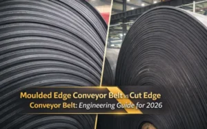
In modern conveyor belt systems using synthetic fabric carcasses, moulded edge conveyor belt is not inherently superior to cut edge conveyor belt. In many high-tension and real-world operating conditions, cut edge structures deliver more predictable stress distribution, better splice symmetry, and lower long-term maintenance risk. This article explains why edge design is often the first failure point, and how material systems, alignment behavior, and operating environments determine when moulded edge is mandatory—and when cut edge is the more rational engineering choice.
1.Why Edge Design Directly Affects Conveyor Belt Failure
Molded edge conveyor belt and cut edge conveyor belt—In my years of providing technical support and selection consultation, some clients have reported that the edges are the first to fail.
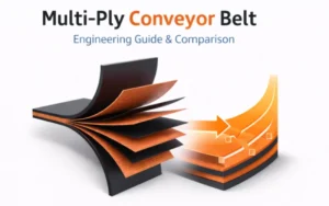
From a structural mechanics perspective, the edges are the areas where lateral stress, misalignment, and moisture intrusion are most concentrated. In multi-layered, the transverse fabric and longitudinal reinforcement layers “terminate” at the edges, naturally creating stress concentration points. Once misalignment occurs, the exposed fabric of a cut edge conveyor belt will be the first to bear the brunt of friction, shear, and environmental erosion; while a molded edge conveyor belt, with its rubber completely covering the edges, isolates stress and environmental factors.
However, the edge type is actually a choice made primarily for structural safety. It directly affects three things:
- Splice quality (how easily the edge peels off, how easily water gets in)
- Production efficiency (whether a longer minimum production length is required)
- Long-term operating costs (premature failure vs. stable lifespan)
If you ask me, how to select between a molded edge belt and a cut edge belt? My first question would be, “What is your application scenario?” This would help me determine which edge type is more suitable for your needs.
Therefore, the real difference between a molded edge conveyor belt and a cut edge conveyor belt goes far beyond what you see on a quote.
2.The Two Conveyor Belt Edge Types That Actually Matter
In real-world engineering and procurement scenarios, I suggest simplifying your choices. You only need to focus on two edge types: molded edge conveyor belts and cut edge conveyor belts. From a purely manufacturing perspective, cut edge conveyor belts are not cheaper than molded edge conveyor belts; in fact, they are usually more expensive. This is a matter of manufacturing logic, not marketing rhetoric.
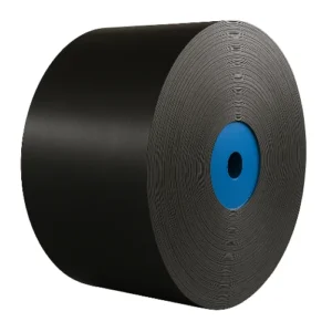
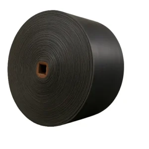
2.1 Molded Edge Conveyor Belt — A One-Piece Molded Structural Solution
From a manufacturing perspective, the logic behind molded edge conveyor belts is very clean.
The edges are completed simultaneously during molding and vulcanization, with the rubber naturally covering the fabric carcass, eliminating the need for subsequent cutting processes.
The direct results are:
- Continuous edge structure and clear stress path
- Higher tolerance for edge water seepage and interlayer delamination
- Shorter process path, but with specific requirements for equipment and width conditions
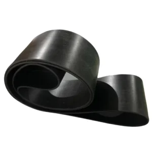
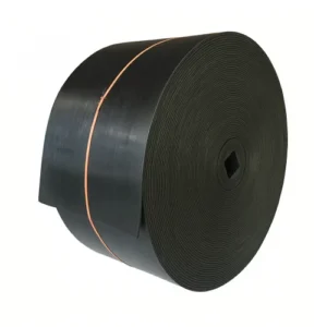
2.2 Cut Edge Conveyor Belt — Subsequent processes determine the structural form
After vulcanization, the cut edge conveyor belt is longitudinally cut (slitting) to obtain the finished width, exposing the fabric edge.
Here’s an engineering fact that must be clarified: The cut edge conveyor belt is not “simpler in process,” because it involves an additional, indispensable subsequent cutting process compared to molded edge, requiring higher standards for dimensional control and edge consistency.
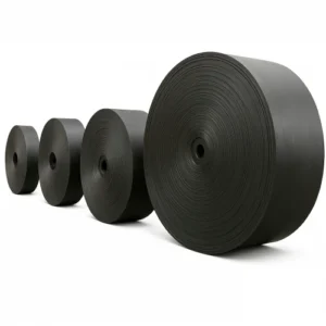
2.3 When Width Becomes a “Structural Boundary Condition”
In actual production, when the finished product width enters the narrow band range (typically <300 mm) , the situation fundamentally changes:
- Due to limitations imposed by the molding drum structure, layup stability, and vulcanization stress,
- molded edge conveyor belts are difficult to manufacture stably within this width range, resulting in a significant decrease in yield.
Therefore, in this scenario:
cut edge conveyor belts are not a “more economical choice,” but rather the only realistically feasible structural form.
For this reason, in narrow band applications,the difference between cut edge and molded edge is not a selection issue, but a manufacturing boundary issue.
3.Why Moulded Edge Conveyor Belt Is Often Over-Specified
To put it simply, the insistence on molded edge conveyor belts in many projects today is essentially a legacy of history, not an engineering necessity.
3.1 The Cotton Fabric Era — The Right Solution to an Old Problem
In the early 20th century, the main material for conveyor belt skeletons was cotton fabric.
This was an engineering reality:
- Cotton fibers have a high water absorption rate, reaching 15–25% of their own weight (industry material data).
- Once the edges are exposed, moisture quickly seeps in.
- The result is decreased interlayer adhesion, edge peeling, and premature failure.
In that era, molded edge conveyor belts were perfectly correct, even the only reasonable solution.
Rubber edging wasn’t a “premium feature,” but a necessity for survival.
3.2 Synthetic Fabrics Changed the Game
By the 1960s–1970s, Nylon/Polyester (NN/EP) began to become the mainstream skeleton material.
Here’s a severely underestimated change:
- Synthetic fibers typically have a water absorption rate of <4%.
- Even with cut-edge conveyor belts, the edges will no longer suffer structural failure due to water absorption.
But here’s the problem—the material has changed, but standards and understanding haven’t kept pace.
3.3 Where Over-Specification Comes From
So today you see a common phenomenon:
- Modern operating conditions
- Synthetic fiber skeleton
- Non-corrosive environment
Yet, molded-edge conveyor belts are still “default” specifications,
and no one is truly reassessing whether the difference between cut-edge and molded-edge conveyors belts still holds true under current conditions.
This isn’t technological conservatism, but rather standard inertia.
4. What Is a Moulded Edge Conveyor Belt?
In Tiantie’s manufacturing system, a moulded edge conveyor belt refers to a conveyor belt whose edge structure is designed to the finished width during the molding stage, and whose edge rubber and belt structure are integrally cured and formed during the same vulcanization process.
The edge shape is determined upon completion of vulcanization and does not rely on subsequent cutting to obtain the final edge. The finished conveyor belt’s edge dimensions, shape, and structural state are its final state after it leaves the production line.
4.1 How Moulded Edge Belts Are Manufactured
The core of moulded edge conveyor belt manufacturing is molding to the finished width + applying edge sealing strips + direct vulcanization. The process path is clear and does not include unnecessary steps.
4.1.1 Manufacturing Process:
1.Determine the Finished Width
Based on the customer’s working conditions, equipment structure, and installation conditions, first determine the final finished width and allowable tolerances. Production is then organized according to this width during the molding stage.
2.Edge Sealing Strip Application During Molding
During the conveyor belt molding process, edge sealing strips are applied to both sides of the belt body, ensuring a complete rubber edge structure before vulcanization.
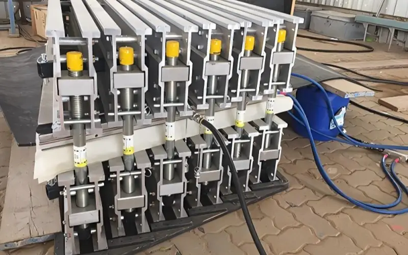
3.Steel Strip Control During Vulcanization
During vulcanization, steel strips are placed along the finished width of the conveyor belt on both sides, tightly against the belt edge. This restricts lateral flow of rubber under high temperature and pressure conditions, ensuring stable edge dimensions and straight edges.
This process does not require folding the rubber or rely on any special molds.
4.Standard Vulcanization Cycle Curing
Vulcanization time is strictly adhered to the validated rubber compound formulation and performance requirements of the Tiantie laboratory, without any additional extension of vulcanization time due to the molded edge conveyor belt structure.
4.1.2 Process Boundaries and Delivery Capabilities:
- No dedicated molds required
- No extra-wide cutting required
- Minimum order quantity: 100 m
- Under the same conditions, production cycle is typically shorter than cut edge conveyor belts.
4.2 Structural Characteristics of Moulded Edge Conveyor Belts
From a finished product perspective, the edge characteristics of a moulded edge conveyor belt are very clearly defined.
4.2.1 Edge Morphology
The edge is a vertical edge perpendicular to the belt surface, without rounded or sloping transitions.
4.2.2 Thickness Consistency
The edge thickness is consistent with the main belt body. A stable moulded edge conveyor belt does not rely on “edge thickening” to achieve structural or protective purposes.
4.2.3 Structural Continuity
The edge rubber cures synchronously with the belt body during vulcanization, and the edge structure is locked in during the manufacturing stage.
4.2.4 Fold-Free Structure
There are no folding steps in the process, and structurally there are no folded areas, fold boundaries, or localized reinforcement areas.
4.3 Typical Advantages and Limitations
4.3.1 Advantages:
- Formed to finished width, eliminating the need for subsequent edge trimming, resulting in a more direct overall production flow.
- No need for extra-wide cutting, resulting in high material utilization and lower costs compared to cut-edge conveyor belts.
- Low minimum order quantity (100 m), making it more suitable for project replenishment and maintenance needs.
4.3.2 Limitations:
- Edge quality is highly dependent on the forming fit and steel strip positioning accuracy.
- Long-term belt misalignment will still affect the edges first, requiring high standards for equipment alignment and on-site management.
5.What is a Cut Edge Conveyor Belt?
A cut edge conveyor belt refers to a conveyor belt structure where the final edge is formed directly through longitudinal cutting after molding and vulcanization.
The cut edge is the finished edge; its shape, width, and straightness are all determined in one cutting process.
This structure is very common in fabric conveyor belts and is a standard production method in many factories.
5.1 How Cut Edge Conveyor Belts Are Manufactured
The manufacturing process of a cut edge conveyor belt is not complex; the key lies in how the cutting process is consistently and precisely executed.
Manufacturing Process:
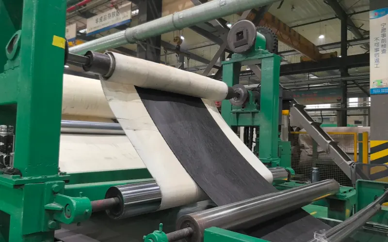
1.Belt Molding and Vulcanization
The conveyor belt is molded and vulcanized according to the design structure. The cover rubber and fabric carcass are cured as a whole during this stage.
2.Longitudinal Cutting (Slitting)
After vulcanization, the finished width is cut using longitudinal cutting equipment according to order requirements.
3.Finished Product Inspection
The straightness, width tolerances, and cut surface condition of the cut edge are inspected to confirm compliance with customer quality requirements.
It should be clarified :
Cut-edge conveyor belts are generally only suitable for fabric conveyor belts.
Steel cord conveyor belts are not suitable for cut-edge structures; there is no technological prerequisite for defining the edge through longitudinal cutting.
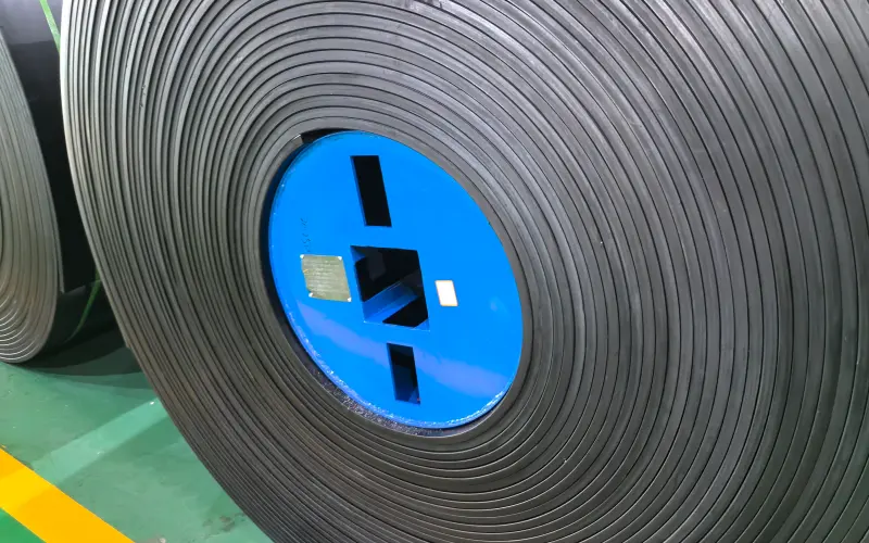
5.2 Structural Characteristics of Cut-Edge Conveyor Belts
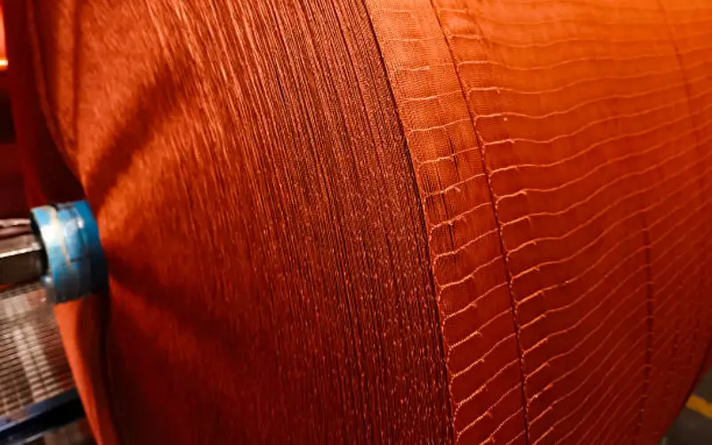
Structurally, the edges of cut-edge conveyor belts have very intuitive and observable characteristics.
1.The carcass layer cross-section is clearly visible.
The fabric is neatly cut at the edge, and the cut surface is directly exposed, serving as the termination interface of the belt structure.
2.The edge morphology is entirely determined by the cut.
The straightness, flatness, and consistency of the edge depend on the precision and operational stability of the cutting equipment.
3.The cut surface provides structural readability.
The arrangement and forming quality of the fabric can be directly observed through the cut edge cross-section.
5.3 Typical Advantages and Limitations
5.3.1 Advantages:
- Direct process path, mature manufacturing process
- Flexible width specifications; multiple finished product specifications can be cut from the same master belt
- Product quality can be judged through the cut surface
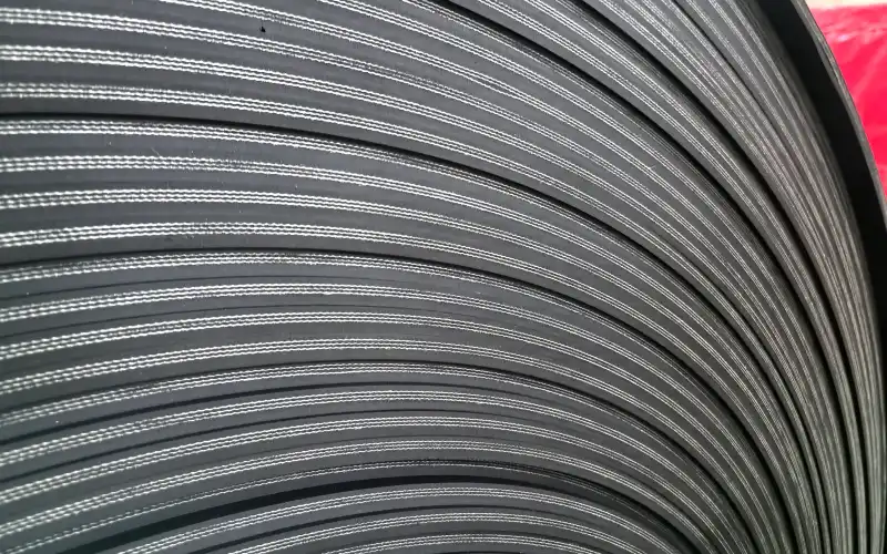
In actual production, if the forming process is not properly controlled, the fabric carcass often exhibits wavy lines or uneven arrangement.
By observing the cut edge cross-section, the number of wavy lines in a conveyor belt can be clearly seen, thus providing a direct assessment of its forming quality. This quality identification method cannot be achieved on molded edge conveyor belts.
5.3.2 Limitations:
- The edge is the structural termination surface, making it more prone to early wear under long-term misalignment or lateral friction conditions.
- Edge quality is highly dependent on the condition of the cutting equipment and the level of process control.
6.Key Structural Differences Between Moulded Edge and Cut Edge Belts
6.1 Edge Protection and Exposure of Fabric Plies
6.1.1 Moulded Edge
- The ends of the fabric plies are completely encapsulated by rubber
- The edge is physically isolated from the external environment
- The edge itself provides no visible information about the carcass plies
6.1.2 Cut Edge
- The ends of the fabric plies are directly exposed at the cut cross-section
- Edge performance depends on the inherent water resistance and chemical stability of the fabric material
- The cut surface is clearly visible, allowing direct observation of the carcass condition
6.1.3 Engineering Reality
In the vast majority of industrial applications, synthetic fabric carcasses are used.
Within this material system, whether the edge is rubber-covered generally does not result in any measurable performance difference.
6.2 Stress Distribution Across the Belt Width
6.2.1 Moulded Edge
- A structural overlap zone exists at the edge
- A stiffness transition zone is formed between the edge and the main body
- Transverse stress gradients develop at the structural transition area
- The mechanical response of the edge is not fully consistent with that of the central region
6.2.2 Cut Edge
- From the center to the edge, thickness and structure remain consistent
- Overall belt stiffness is continuous across the full width
- Transverse stress distribution is uniform
- Load paths are clear and predictable
6.2.3 Impact in High-Tension Systems
Under long-distance, high-tension operating conditions:
- The stiffness consistency of cut edgebelts promotes uniform stress distribution
- Structural discontinuities in moulded edgebelts may amplify stress differentials in the splice area
6.3 Water Ingress and Long-Term Interface Stability
6.3.1 Historical Background
In the early era of natural fibers, water absorption at the edge would directly lead to interlayer failure.
6.3.2 Modern Material Reality
6.3.3 Moulded Edge
- The edge is completely isolated from the external environment
- Provides a structural advantage under long-term high-humidity or chemical exposure conditions
6.3.4 Cut Edge
- Under normal operating conditions with synthetic fabric carcasses, exposed edges do not lead to interlayer failure
- The only risk arises from extreme long-term immersion combined with poor adhesive systems, a scenario that is very rare in real applications
6.4 Impact on Splicing Geometry and Joint Symmetry
6.4.1 Core Factors Affecting Splice Quality
- Whether edge thickness matches the belt body
- Whether splice geometry is symmetrical
- Whether the bonding interface is continuous
6.4.2 Structural Characteristics of Cut Edge
- Edge thickness is consistent with the belt body
- Splice geometry is inherently symmetrical
- Step cutting is simple, with uniform step heights across plies
- Bonding area can be fully developed
- Splice strength stably reaches 85–90% of belt strength (common industry level)
6.4.3 Structural Impact of Moulded Edge
- Structural overlap exists at the edge
- Compensation is required for the edge area in the splice region
- Step cutting is more complex, and top/bottom surfaces are difficult to keep fully symmetrical
- Uniform bonding at the edge area is harder to achieve
- Splice strength typically falls within the 75–85% range
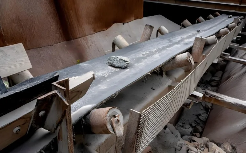
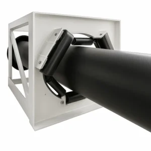
6.5 Tolerance to Belt Misalignment and Edge Contact
6.5.1 Operating Premise
Some degree of belt misalignment is unavoidable in any conveying system.
Once misalignment occurs, the belt edge is always the first area to contact guide devices or support structures.
6.5.2 Moulded Edge
- The structural overlap zone at the edge becomes the primary contact point
- Local stress concentration makes edge delamination more likely
- Once delamination occurs, damage may propagate across the belt width
- On-site repair of edge damage is relatively difficult
6.5.3 Cut Edge
- No structural overlap at the edge, resulting in a smaller contact area
- Stress is more dispersed; damage typically manifests as cover rubber wear
- Cover rubber wear usually does not lead to structural degradation
- The edge is easier to repair on site
6.5.4 Comparison Under Actual Operating Conditions
- Minor misalignment (<5 mm):little difference between the two edge types
- Moderate misalignment (5–15 mm):cut edge belts show 20–30% lower edge wear rates
- Severe misalignment (>15 mm):moulded edge belts have a 3–5 times higher risk of edge delamination
7.Performance Comparison in Real Industrial Conditions
In real industrial field applications, the performance differences between moulded edge conveyor belt and cut edge conveyor belt depend on the characteristics of the operating system itself.
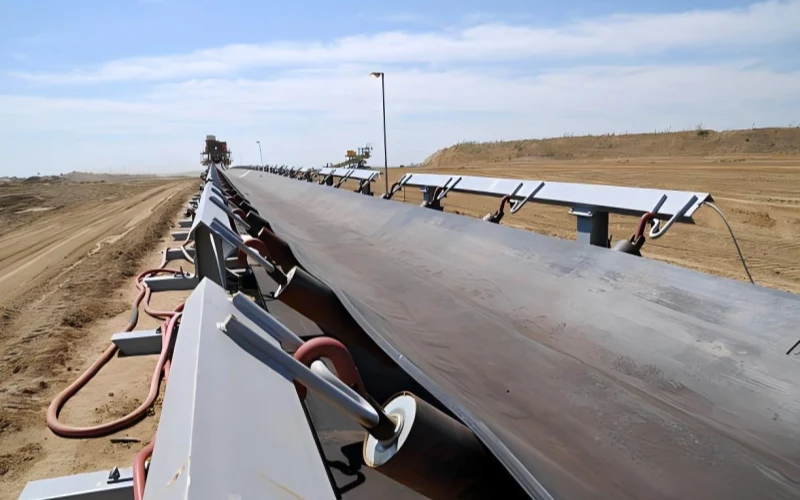
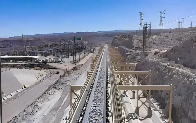
7.1 High-Tension and Long-Distance Conveying Systems
7.1.1 System characteristics :
- High-strength fabric carcass construction
- Conveying distance typically > 1.5–2 km
- Operating tension near the upper limit of fabric conveyor belts
- splice subjected to long-term cyclic loading and fatigue stress
In such systems, the long-term stability of the splice is the key factor determining service life.
7.1.2 Actual performance of Cut Edge:
1.Stress uniformity
- Belt thickness and structure are consistent from center to edge
- Transverse load distribution is uniform
- splice geometry is symmetrical, with low stress concentration
- Stable long-term fatigue performance
2.Splice reliability
- No edge thickness compensation required
- High precision and repeatability of step cutting
- Uniform bonding interface
- Actual splice strength can stably reach 88–92% of belt strength
3.Maintenance convenience
- Minor edge damage does not affect splice geometry
- Edge cover rubber can be directly trimmed prior to splicing
7.1.3 Structural limitations of Moulded Edge under these conditions:
- Structural overlap exists at the edge
- Under high-tension cyclic loading, stiffness differences between the edge and the belt body are more easily amplified
- The edge area of the splice is more likely to become a fatigue weak point
- After long-term operation, there is a risk of microscopic delamination at the edge structural interface
7.2 Wet, Muddy, or Poorly Controlled Environments
7.2.1 Environmental characteristics:
- High humidity (>85% RH)
- Frequent contact with water or mud
- Delayed or insufficient cleaning and maintenance
- Large ambient temperature fluctuations
Under Nylon / Polyester synthetic fabric carcass conditions, edge-type differences show different characteristics over different operating periods.
7.2.2 Actual performance of Cut Edge:
- Short-term operation (<2 years):no obvious performance difference
- Mid- to long-term operation (2–5 years):
- Local wear or slight peeling of edge cover rubber may occur
- Fabric carcass structure is not affected
- Typical failure mode:
- Surface cover rubber wear
- Can be repaired on site
7.2.3 Actual performance of Moulded Edge:
- Short-term stage:
- Edge remains sealed with intact appearance
- Long-term risk points:
- If bonding control at the edge structural interface is insufficient
- Moist media may accumulate at the interface
- Once delamination initiates, damage may propagate along the belt width
7.3 Systems with Frequent Belt Misalignment
7.3.1 Common causes of misalignment:
- Insufficient installation accuracy of idler sets
- Uneven material distribution
- Conveyor structure deformation
- Environmental factors (wind load, temperature differentials)
7.3.2 Structural performance of Cut Edge:
- No structural overlap at the edge
- Small contact area with dispersed stress
- Wear mainly concentrated in the cover rubber
- Low risk of progressive failure
- Edge can be repaired by cold bonding or hot bonding
7.3.3 Structural performance of Moulded Edge:
- Edge structural overlap area becomes the primary contact point
- Local stress concentration
- Once edge delamination initiates, propagation speed is high
- On-site repair is difficult and usually requires full belt replacement
7.3.4 Comparison under actual operating conditions:
- Misalignment < 3 mm: similar service life for both edge types
- Misalignment 3–10 mm: cut edge service life extended by 15–25%
- Misalignment > 10 mm: cut edge service life extended by 30–50%
7.4 Maintenance-Limited or Remote Operations
7.4.1 Typical scenarios:
- Remote mining conveying systems
- Continuous port operation systems
- Unattended facilities or sites with limited maintenance windows
7.4.2 Operational advantages of Cut Edge:
- Standard stock can be quickly cut to different widths
- Emergency replacement cycle typically 2–5 days
- Edge can be temporarily repaired to extend operating time
- splice can be completed on site without edge compensation
7.4.3 Operational limitations of Mould Edge:
- Custom production cycles typically 15–30 days
- Advance stocking of common widths required, tying up capital
- Edge structural damage is difficult to handle on site
7.4.4 Operating cost comparison:
- cut edge:inventory costs can be reduced by 30–40%
- moulded edge:higher inventory pressure and capital occupation
8.Why Cut Edge Belts Often Perform Better in High-Tension Systems
In high-tension conveying systems, cut edge conveyor belt often exhibits more stable and more predictable structural responses. This is because under high-tension conditions, force paths, strain consistency, and splice symmetry are continuously amplified, and cut edge belts have inherent advantages at these critical structural points.
8.1 Force Path Clarity
8.1.1 Cut Edge
- Load transfer paths are clear:
From pulley → fabric plies → uniformly distributed across the full belt width - The mechanical response of the edge is consistent with that of the central region
- No local structural overlap or stiffness discontinuity
- Stress distribution is easier to calculate and predict from an engineering standpoint
8.1.2 Moulded Edge
- Structural overlap exists at the edge
- Local stiffness variations form between the edge and the belt body
- Load deflection and concentration occur in the edge region
- Edge geometry is more complex, making stress distribution modeling more difficult
8.1.3 Practical differences under high-tension conditions
As operating tension approaches the upper limit of fabric carcass systems, these differences gradually become apparent:
- Under low to medium tension: structural differences have limited impact
- As tension continues to increase: the stress uniformity advantage of cut edge is progressively amplified
- During long-term operation: the edge region of moulded edge belts is more likely to become a local fatigue initiation point
8.2 Transverse Strain Consistency
8.2.1 Operating background
During belt operation, transverse strain occurs each time the belt passes over a pulley:
- Cyclic loading causes transverse contraction and recovery
- In high-tension systems, the amplitude of transverse strain can be significantly amplified
8.2.2 Structural response of Cut Edge
- Transverse strain is consistent across the entire belt width
- The edge and central regions contract and expand synchronously
- No localized strain concentration zones exist
- Under long-term cycling, fatigue accumulation is more uniform
8.2.3 Structural response of Moulded Edge
The structural overlap at the edge constrains transverse deformation
Strain gradients are generated at the boundary of the edge structure
Under long-term cyclic loading, this area is more prone to fatigue damage accumulation
8.2.4 Engineering observation data
Under long-term cyclic operating conditions:
- cut edge: no obvious fatigue signs observed at the edges
- moulded edge: microscopic fatigue cracks observed in some samples at the edge structural boundary
8.3 Splice Symmetry (Importance of Splice Symmetry)
8.3.1 Engineering reality of splices
- The splice is the weakest structural link in the entire conveyor belt
- Even with fully qualified processes, splice strength typically reaches only 85–92% of belt strength
- In actual failure cases, splice-related issues account for more than 70%
8.3.2 Advantages of Cut Edge in splice structure
1.Geometric symmetry
- Edge thickness is consistent with the belt body
- Top and bottom surfaces are fully symmetrical
- Step-cut heights are uniform
- Bonding area can be maximized
2.Stress symmetry
- Stress distribution in the splice area is symmetrical
- No local stress concentration at the edge
- Lowest risk of delamination
8.3.3 Structural challenges of Moulded Edge at the splice
1.Geometric asymmetry
- Structural overlap at the edge results in inconsistency between top and bottom surfaces
- Step cutting requires compensation adjustments in the edge area
- Effective bonding area is reduced by approximately 5–8%
2.Stress asymmetry
- The edge region of the splice is more prone to stress concentration
- Edge splices become the preferred failure location
- After long-term operation, the risk of edge splice delamination increases significantly
9.Why Moulded Edge Belts Are Preferred in Harsh and Unstable Conditions
In certain industrial environments, the risks faced by conveyor belts do not come from tension or splice performance, but from the uncontrollability of the environment itself. In these scenarios, the value of a moulded edge conveyor belt is not reflected in being “higher performance,” but in making failure less likely to occur.
9.1 Environmental Tolerance
Under the following environmental conditions, moulded edge conveyor belt is often irreplaceable.
9.1.1 Continuous Exposure to Strong Acidic or Alkaline Environments
1.Environmental characteristics:
- pH < 3 or pH > 11
- Long-term, repeated contact of chemical media with belt edges
- Frequent cleaning, with chemical residues difficult to fully remove
2.Practical risks of Cut Edge:
- Fabric ply ends are directly exposed
- Chemical media can penetrate along the capillary structure of the fabric plies
- Under long-term exposure, the adhesive interface gradually degrades
3.Structural advantages of Moulded Edge:
- Edge rubber forms a continuousstructure
- Fabric ply ends are completely isolated from external chemical media
- Capillary penetration paths are effectively blocked
In such environments, edge sealing itself is the core protection mechanism.
9.1.2 High Temperature + High Humidity + Long-Term Immersion Conditions
1.Typical conditions:
- Continuous immersion time accounts for >50% of operating time
- Ambient temperature >60 °C
- Relative humidity >90%
2.Potential risks of Cut Edge:
- Under extreme combined conditions
- Adhesive interfaces may experience long-term performance degradation
- The risk comes from “long-term accumulation,” not short-term failure
3.Structural response of Moulded Edge:
- prevent water ingress along fabric ply ends
- Reduces the probability of long-term interface degradation caused by prolonged immersion
It must be emphasized that:
Such risks are only of engineering significance under extreme, long-term combined conditions, not in ordinary wet environments.
9.2 Edge Durability
In some systems, the edge is not in “occasional contact,” but is continuously involved in friction and impact.
1.Typical scenarios where Moulded Edge has an advantage:
- Poorly designed guiding devices
- Skirtboard clearances that are too small
- Limited conveyor width, leaving insufficient edge movement space
2.Structural protection mechanisms:
- Additional rubber layers at the edge provide cushioning
- Wear occurs first in the rubber layer
- Fabric plies do not directly participate in friction
Under the premise of good alignment but frequent edge contact,the edge wear life of moulded edge can be extended by 30–50%.
3.Prerequisites that must be clearly stated:
- This advantage only applies to well-aligned systems
- Once significant misalignment occurs
- The structural overlap at the edge instead becomes a high-risk point
9.3 Failure Mode Management
What truly differentiates the value of the two edge types is not “whether failure occurs,” but how failure occurs and how controllable it is.
1.Failure mode of Cut Edge:
- Primary form: edge cover rubber wear
- Failure progression: gradual and predictable
- Structural consequence: cosmetic damage, fabric plies remain intact
- Repair method: on-site repair possible, service life can be extended
2.Failure mode of Moulded Edge:
- Primary form: delamination at the edge structural interface
- Failure progression: once initiated, propagation is rapid
- Structural consequence: structural damage at the edge
- Repair method: usually requires full belt replacement
3.Engineering-level interpretation:
- Cut edge:failure is manageable, repairable, and progressive
- Moulded edge:more durable under normal operating conditions, but once failure occurs, the cost is higher
10.Total Cost of Ownership: Beyond Initial Price
In practical engineering decision-making, the choice between moulded edge conveyor belt and cut edge conveyor belt is essentially a TCO (Total Cost of Ownership) issue rather than a simple unit price comparison.
Even when the minimum order quantity for both edge types is the same at 100 m, long-term costs will still gradually diverge in terms of delivery efficiency, inventory structure, maintenance methods, and downtime risk.
10.1 Production Efficiency and Lead Time
First, it is necessary to clarify a commonly misunderstood fact:
for Tiantie’s actual production, the minimum order quantity for both cut edge and moulded edge is 100 m.
What truly creates the difference is not the MOQ, but the production organization method and width flexibility.
10.1.1 Production and Delivery Characteristics of Cut Edge
- Production process:standard vulcanization → cut to demand → delivery
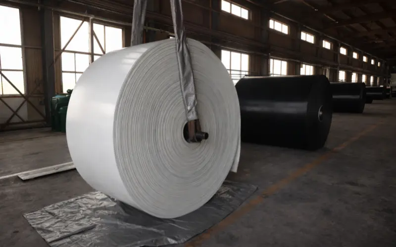
- Inventory utilization:
Standard-width master rolls (e.g. 1200 mm) can be cut into multiple finished widths - Lead time:
2–5 days when inventory is available - Minimum order quantity:
100 m - Width flexibility:
Different widths can be cut according to demand, with accuracy controllable within ±5 mm
10.1.2 Production and Delivery Characteristics of Moulded Edge
- Production process:forming to finished width → vulcanization → delivery
- Production organization:
Although the minimum order quantity is also 100 m, each width requires separate production scheduling - Lead time:
Typically 15–30 days, depending on current production scheduling and mould availability - Width flexibility:
Width is fixed before production and cannot be adjusted later by cutting
10.1.3 Typical Efficiency Difference (300 mm Width Requirement)
- cut edge:
Can be quickly delivered by cutting directly from 1200 mm standard stock - moulded edge:
Even if only 100 m is required, separate forming and vulcanization must be arranged for the 300 mm width - Impact on time cost:
In actual projects, the average delivery cycle of moulded edgeis still approximately 15–20 days longer than that of cut edge.
10.1.4 Inventory Management Differences
- Cut edge strategy:
Stock a small quantity of standard widths to cover multiple requirements - Moulded edge strategy:
Stock inventory separately for each commonly used width - Resulting inventory cost:
Capital tied up in moulded edgeinventory is typically still 40–60% higher.
10.2 Maintenance and Repair Cost Differences
The handling of edge damage is a key dividing line in long-term cost.
10.2.1 Cut Edge
- Typical damage form:edge cover rubber wear
- On-site repair methods:
- Cold bonding strips: ~30 minutes, cost <$50
- Hot repair: ~2 hours, cost <$200
- Repair effect:
Service life can be extended by 3–12 months - Downtime:
5–2 hours
10.2.2 Moulded Edge
- Typical damage form:delamination at the edge structural interface
- On-site repair feasibility:
- Minor delamination: bonding repair may be attempted, success rate <50%
- Obvious delamination: usually not repairable on site
- Common result:
Full belt replacement required - Downtime:
4–8 hours (replacement + splice)
10.3 Impact of Splice Interval and Cost
10.3.1 Cut Edge
- Splice interval:4-5 years
- Splice cost:$2,000–5,000 per event
10.3.2 Moulded Edge
- Splice interval:3-4years
- Splice cost:$2,500–6,000 per event
10.3.3 Annual maintenance cost comparison (1000 m system):
- cut edge:$800–1,200 / year
- moulded edge:$1,200–2,000 / year
→ typically 20–40% higher
10.4 When Higher Initial Cost Justifies ROI
Even with the same MOQ, the initial procurement cost of moulded edge is usually higher than that of cut edge. Whether it is justified depends on whether it delivers quantifiable long-term returns.
10.4.1 Scenarios Where Moulded Edge ROI Is Justified
1.Continuous exposure to strong acids and alkalis
- Initial cost increase: 15–25%
- Avoided cost: interlayer delamination caused by chemical corrosion
- Potential savings: 30–50%
- ROI period: 12–18 months
2.High humidity + long-term immersion conditions
- Initial cost increase: 15–25%
- Avoided cost: long-term degradation of the edge interface
- ROI period: depends on operating life and maintenance frequency
3.Remote or high-reliability systems
- Initial cost increase: 15–25%
- Avoided cost: unplanned downtime losses
- Single downtime loss: $5,000–50,000
- ROI period: typically 6–24 months
10.4.2 Scenarios Where Cut Edge ROI Is Justified
1.Standard operating conditions, synthetic fabric carcass systems
- Initial cost saving: 15–30%
- Short lead time reduces downtime waiting costs
- 5-year TCO saving: 20–35%
2.Multiple width specifications or small-batch demand
- Initial procurement cost saving: 15–30%
- Inventory cost saving: 40–60%
- Effectively avoids overstocking
3.Systems with unstable alignment conditions
- Edge damage is controllable and repairable
- Lower long-term maintenance cost
- TCO saving:25–40%
10.5 Decision Formula
TCO = Initial Procurement Cost + (Annual Maintenance Cost × Service Life) + (Downtime Loss × Downtime Frequency) + Inventory Holding Cost
11. Special Cases: When Edge Type Is Not a Choice
In most fabric carcass conveyor belt applications, cut edge conveyor belt and moulded edge conveyor belt can be selected through operating-condition trade-offs.
However, in a small number of scenarios that are strongly constrained by regulations, material systems, or usage conditions, edge type is not optional but is directly dictated by technical requirements.
11.1 Fire-Resistant Belts
Within fire-resistant conveyor belt systems, the edge structure is part of the compliance requirement rather than a performance optimization option.
11.1.1 Technical and standards background
In standards systems represented by DIN 22103 (fire-resistance classification), there is a clear structural prerequisite:
The cover rubber must continuously encapsulate the fabric plies, and exposed fabric paths at the belt edge are not permitted.
11.1.2 Engineering rationale
Once fabric plies are exposed at the edge,under flame, high-temperature, or thermal radiation conditions,they can become channels for flame propagation and heat transfer,directly undermining the integrity of the belt’s fire-resistant system.
11.1.3 Edge type conclusion
- For fire-resistant conveyor belt applications:
→ moulded edge must be used - cut edgedoes not meet the structural requirement of continuous edge coverage mandated by fire-resistant systems.
11.1.4 Typical application environments
- Underground or semi-enclosed spaces
- Tunnels and underground conveyor belt projects
- Material conveying systems with high fire risk
In these scenarios, the essence of edge type selection is compliance with fire-resistant structural prerequisites.
11.2 Oil-Resistant and Chemical-Resistant Cover Compounds
When oil-resistant or chemical-resistant cover compounds are used, the edge structure directly affects the long-term stability of the bonding interface.
11.2.1 Material characteristics of special cover compounds
- High filler formulations
- High carbon black and plasticizer content
- Compared with general-purpose cover compounds, bonding strength to fabric plies is typically 10–20% lower
11.2.2 Engineering risks of Cut Edge
- Fabric ply ends are directly exposed
- Chemical media can enter the bonding interface along the capillary structure of the fabric
- Under continuous exposure, interface degradation accelerates significantly
11.2.3 Structural role of Moulded Edge
- Forms continuous rubber encapsulation at the edge
- Isolates fabric ply ends from chemical media
- Effectively blocks capillary penetration paths
11.2.4 Engineering selection logic
- Strong acid or alkali environments(pH < 4 or > 11, continuous exposure):
→ moulded edge is a mandatory structural choice - Oil-resistant environments:
- Intermittent contact: cut edgeis acceptable
- Continuous contact: moulded edgeis preferred
The basis for this judgment is the intensity and duration of chemical exposure, not the inherent “strength” of one edge type over the other.
11.3 Food-Grade and Light-Colored Cover Belts
In this category of applications, edge type selection is driven more by usage specifications and customer expectations than by structural limits.
11.3.1 Practical requirement characteristics
- White or light-colored cover rubber
- High requirements for cleanliness and visual consistency
- Edge condition directly affects acceptance results
11.3.2 Practical impact of Cut Edge
- The color of exposed fabric ply ends contrasts clearly with the cover rubber
- Often unacceptable in food, pharmaceutical, and similar industries
11.3.3 Common engineering choice
- moulded edge, to ensure visual consistency between the edge and the belt surface
11.3.4 A point that must be clarified
This is a requirement driven by specifications and aesthetics,not because cut edge is structurally or mechanically unusable.
If the customer explicitly accepts the visual difference, cut edge remains technically valid.
12.Final Takeaway
Between moulded edge conveyor belt and cut edge conveyor belt, the relationship has never been one of “higher vs. lower specification,” but rather of whether the choice is forced by conditions.
In modern synthetic fabric conveyor belt systems, cut edge covers the vast majority of real operating conditions and has no inherent disadvantages in terms of service life, maintenance, lead time, or total cost.
moulded edge is only justified in a limited number of scenarios where standards, chemical environments, or risk-related costs explicitly push the application in that direction.
If, during selection, you find yourself repeatedly needing to explain “why moulded edge must be used,”
the answer is usually already clear.
When the justification is not strong enough, cut edge is the correct choice.
13.FAQ
1. Do all fabric ply waviness issues originate during the forming stage?
Not necessarily.
At present, the vast majority of waviness seen in the market does occur during the forming stage, but a small portion of cases originate in the calendering stage.
When manufacturers use lower-quality calendering rubber, adhesion between the calender rolls and the rubber compound can occur during calendering. This leads to localized areas where the calendered rubber thickness is significantly greater than normal.
When this uneven rubber layer is then laminated with the fabric carcass and enters the vulcanization stage, differences in local flow and shrinkage ultimately cause fabric ply waviness to form during vulcanization.
2. Why does edge quality vary so much between different factories, even for cut edge conveyor belts?
Because the quality of cut edge belts is highly dependent on upstream manufacturing consistency, not on the cutting operation itself.
The factors that truly create the difference include:
- Stability of fabric tension during forming
- Uniformity of bonding between cover rubber and carcass
- Whether edge behavior is controlled during vulcanization (e.g. lateral rubber flow)
Edge cutting merely exposes the structural outcome—it does not “create problems.”
What you are seeing is essentially manufacturing capability differences being magnified at the cut cross-section.
3. Under what circumstances would a project switch from moulded edge to cut edge at a later stage?
This situation is indeed uncommon. In systems with clear specifications and stable project schedules, it almost never occurs.
However, in a small number of unplanned or emergency scenarios, such adjustments may still happen. Typical characteristics include:
- Sudden conveyor system failure requiring rapid restoration of operation
- Original design specifying moulded edge, but delivery lead time cannot match the site window
- Temporary technical evaluation confirms that:
- There is no mandatory fire-resistance requirement
- There is no continuous exposure to strong acids or alkalis
- A synthetic fabric carcass is used
In these exceptional cases, the engineering team’s focus shifts from
“the optimal solution under specifications” to:
“How to restore system operation as quickly as possible within controllable risk.”
In this context, cut edge is not viewed as a “substitute,”
but as a temporary engineering decision balancing time, risk, and availability.
It must be emphasized that:
this is not a standard selection pathway and should not be treated as a default strategy during the design phase.
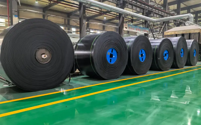
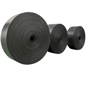
4. How can manufacturing reliability be quickly assessed without destructive testing?
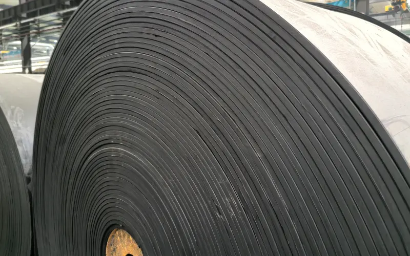
A very practical yet often overlooked method is to observe the conveyor belt roll in its naturally relaxed state.
Focus on three aspects:
- Whether abnormal transverse undulation is present
- Whether there are localized “soft” or “hard” zones in the belt
- Whether belt condition is consistent across different positions within the same roll
A conveyor belt with stable manufacturing control should exhibit an overall uniform state with no rhythmic deformation, even without applied tension.
5. Why do experienced engineers often prefer cut edge over moulded edge?
The reason is straightforward:
cut edge exposes structural issues earlier instead of “sealing them in.”
From an engineering perspective:
- The cut cross-section allows direct observation of fabric ply arrangement
- Splice geometry is more symmetrical
- Edge damage modes are more predictable and repairable
For those responsible for long-term system operation and maintenance,
“inspectable, repairable, and controllable” is often more important than “looking thicker or more robust.”