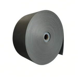
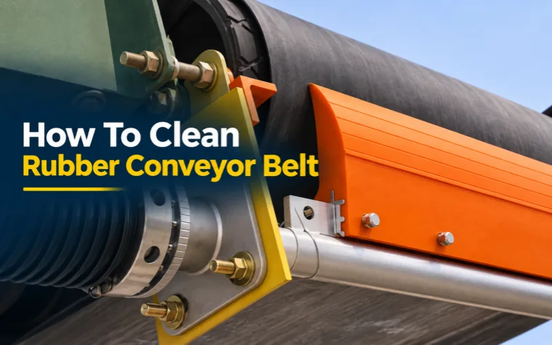
The simplest way to clean a conveyor belt is to install a fixed conveyor belt scraper or a conveyor belt rotary brush, depending on the operating conditions, to continuously clean the return run of the heavy-duty rubber conveyor belt during operation. These devices primarily remove residual material adhering to the carrying surface after unloading, reducing material spillage and accumulation on the return run.
Different materials for the scrapers and multiple scrapers should be selected based on material characteristics, belt surface structure, joint type, and on-site installation conditions. The cleaning effect also depends on whether the cleaning components can maintain stable contact with the belt surface. Excessive contact will cause excessive wear on the scraper and conveyor belt, resulting in excessively large gaps at the contact points, preventing the smooth removal of residual material.
To maintain stable cleaning performance, the cleaning device also needs maintenance based on the accumulation of material and wear. When manual removal of accumulated material, adjustment, or maintenance is required, the machine should be stopped first, the power supply isolated, and measures taken to prevent dangerous movement of the equipment.
1. Conveyor Belt Cleaning Methods
Cleaning a rubber conveyor belt requires considering both the carrying side and the pulley side. Primary conveyor belt cleaners, secondary conveyor belt cleaners, and rotary brushes mainly remove carryback adhering to the carrying side; return belt cleaners remove loose material from the pulley side, reducing the risk of debris entering between the conveyor belt and the pulleys.
1.1 Primary Conveyor Belt Cleaner
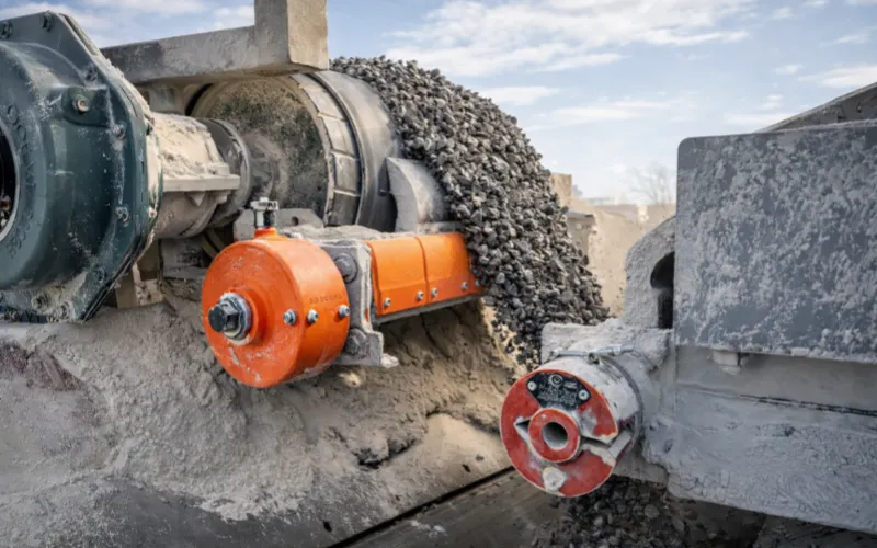
A primary conveyor belt cleaner is usually installed at the head discharge pulley. The blade edge contacts the arc section where the conveyor belt is still wrapped around the pulley after the material leaves the belt, avoiding the normal discharge flow, and scrapes the adhering carryback into the receiving area below.
The pulley provides support for the belt surface, while the spring preload mechanism on the cleaner continuously applies force to the blade. In common designs, springs are installed on the support frame or at the end of the cleaner shaft, allowing the blade position to gradually compensate for wear and maintain contact with the belt surface within the allowable wear travel.
Spring compensation has a travel limit, and the preload also needs to be checked according to the equipment requirements. The blade needs to be replaced after reaching its wear limit. It cannot continue to be used by increasing the spring preload.
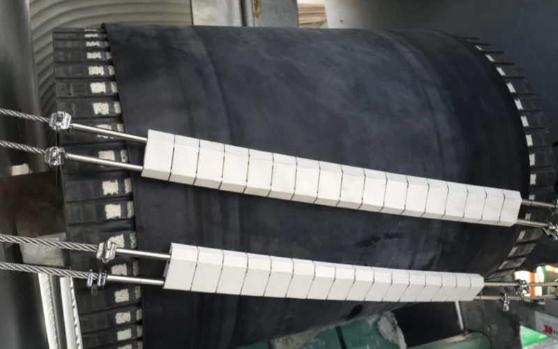
The scraping elements of a primary conveyor belt cleaner can be made of polyurethane, cemented carbide, or ceramic. These materials need to be matched with the corresponding blade structures and loading mechanisms. Ceramic cleaners can also use segmented ceramic blocks and spring mechanisms to accommodate the belt surface.
The effective cleaning width needs to cover the actual material-carrying area, which is usually concentrated in the middle of the belt width. During selection, the actual range of the belt surface contacted by material under normal loading and off-center loading conditions needs to be checked, so that the blade covers the main area where material adheres and leaves an appropriate margin.
There is no universal centimeter value for the side margins of the blade that applies to all models. Based on the dimensions, if the belt width is 1,000 mm and the effective blade width is 800 mm, centering the blade leaves a margin of 100 mm on each side, or 10 cm. This is only a calculation example. The actual dimensions still need to correspond to the material-carrying area and product specifications.
To check the contact condition, after stopping and isolating the conveyor, check whether there are visible gaps within the effective cleaning width, and check the spring preload against the product markings. During operation, the cleaning result can be checked from a safe observation position to confirm whether carryback streaks remain at fixed locations in the main material-carrying area.
1.2 Secondary Conveyor Belt Cleaner
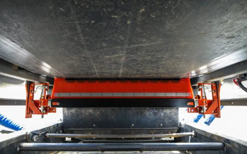
A secondary conveyor belt cleaner is usually installed on the return run after the conveyor belt leaves the head pulley. It still contacts the carrying side, which usually faces downward after entering the return run. The secondary cleaner continues to remove fines and adhered carryback left after primary cleaning.
Secondary cleaners can also use scraping elements made of polyurethane, cemented carbide, or ceramic, and maintain contact through springs or other resilient loading mechanisms. The primary cleaner first reduces the amount of carryback, and the secondary cleaner handles the remaining material, forming a continuous cleaning process for the carrying side.
Secondary cleaning needs to focus on controlling contact load and uniformity of force distribution. When excessive preload, installation misalignment, or unevenness in the belt surface causes local loads to increase, both the blade and cover rubber may wear faster. Therefore, the preload needs to be set according to the equipment requirements to avoid excessive local pressure.
When adding a secondary cleaner, a material receiving location also needs to be arranged. Especially when the device is located outside the existing discharge chute, the scraped carryback needs to be discharged through a receiving plate or guide chute to prevent the removed material from continuing to fall onto the return idlers and equipment structures.
1.3 Rotary Brush Cleaner
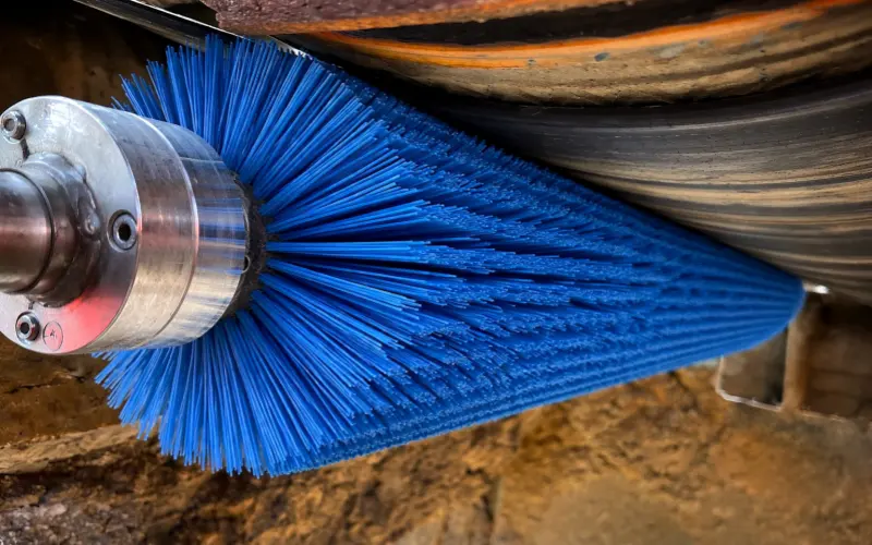
A rotary brush loosens adhering carryback and brushes it off the surface through the relative movement between the bristles and the belt surface. The bristles have a certain degree of flexibility and can contact some patterned and raised-rib areas where straight blade edges have difficulty maintaining continuous contact.
When evaluating chevron conveyor belt cleaning, it is necessary to check whether the bristles can enter between the chevrons and reach the actual material buildup locations. If the bristles only bend over the tops of the raised ribs, carryback may still remain at the roots of the pattern. A close fit in appearance does not mean that cleaning is complete.
The brush’s own ability to discharge carryback also affects continuous cleaning performance. When wet, sticky fines accumulate between the bristles, they reduce the effective brushing space and may also be carried back into the contact area. Therefore, suitability needs to be assessed based on material stickiness and brush structure.
For highly abrasive materials, attention needs to be paid to bristle wear and replacement requirements. For fines that easily generate dust, collection and dust-control measures are also needed so that the material brushed off the belt enters the designated collection location.
1.4 Return Belt Cleaner
A return belt cleaner mainly cleans the pulley side, that is, the bottom cover side. In a common return-run arrangement, the carrying side faces downward and the pulley side faces upward; loose material falling inside the conveyor belt loop may remain on this side.
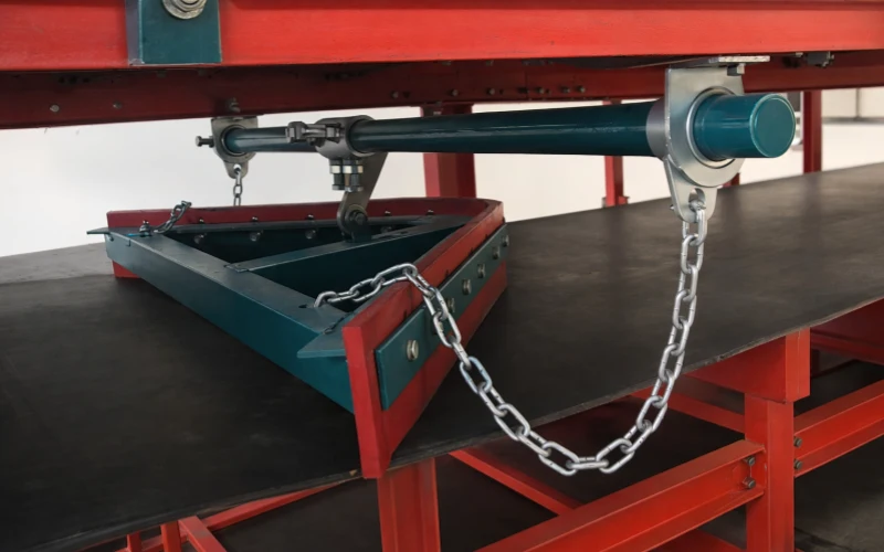
A return belt cleaner is usually installed before the tail pulley and contacts the upward-facing pulley side to remove loose material from the belt surface. Even if the amount of loose material is small, larger particles entering between the conveyor belt and the tail pulley may damage the belt surface under pressure and cause material buildup on the pulley and abnormal operation.
Polyurethane is a commonly used blade material for this type of return belt cleaner. The bottom cover of a heavy-duty bulk material conveyor belt is usually thinner than the top cover, and material on the pulley side mainly comes from abnormal spillage. Therefore, the cleaning arrangement needs to consider both debris removal and protection of the thinner bottom cover.
Common designs include:
- V-shaped return belt cleaner: Diverts debris toward both sides of the conveyor belt through a V-shaped blade, reducing the amount of material continuing toward the tail pulley.
- Straight return belt cleaner: Uses a straight blade to remove debris from the pulley side. The discharge direction needs to be determined according to the blade installation angle and the on-site material receiving arrangement.
Primary, secondary, and rotary brush cleaners mainly remove carryback adhering to the carrying side, while return belt cleaners protect the pulley side and the tail pulley. The material sources and cleaning tasks on the two sides are different, so the corresponding devices need to be arranged separately.

2. How to Select a Conveyor Belt Cleaner for the Operating Conditions
When determining a rubber conveyor belt cleaning solution, material conditions, operating parameters, and installation limitations need to be converted into specific selection requirements. When comparing different quotations, the applicable conditions of the model, as well as the configuration of contact components and spare parts, need to be checked.
2.1 Determine Selection Requirements Based on Material Conditions
Material information needs to specify the particle size range, proportion of fines, changes in moisture content, and adhesion conditions. If the rainy season or changes in the material mix significantly increase adhesion, the material conditions under more difficult cleaning conditions need to be included in the selection, to avoid a solution that only covers dry operating conditions.
When preparing to replace the blade material, the current material, actual service time, and wear photos need to be provided. This information helps determine whether higher abrasion resistance is needed and whether the recommended material can improve the current component consumption rate, avoiding product comparisons based only on material names.
For high-temperature operating conditions, the belt surface temperature at the cleaning position also needs to be recorded, including the sustained temperature and short-term peak temperature. The temperature resistance ranges of the scraper blades, brush bristles, and related resilient components need to be checked separately, to prevent any one component from limiting the applicability of the entire device.
2.2 Check Belt and Equipment Information
Equipment information needs to include belt width, belt speed, running direction, and operating hours. Equipment with variable speed needs to specify the normal belt speed and maximum belt speed. If reverse operation is required, this also needs to be clarified during the selection stage, to confirm whether the specific model allows bidirectional operation.
For the selection of a primary conveyor belt cleaner or secondary conveyor belt cleaner, the mechanical splice type and close-up photos need to be provided.
2.3 Check Configuration Limitations Under Different Operating Conditions
Based on the material and equipment information you provide, we will check the following configuration requirements:
Site Conditions | Information Required | Items We Need to Check |
Mechanical splice present | Mechanical splice type and close-up photos | Compatibility of the blade tip and tensioning mechanism when passing over the splice |
Conveyor belt needs to run in reverse | Normal running direction and reverse operation requirements | Whether the specific model is suitable for the required running direction |
High temperature at the cleaning position | Sustained belt surface temperature and short-term peak temperature at the cleaning position | Temperature resistance ranges of the scraper blades, brush bristles, and related resilient components |
Frequent replacement of existing components | Current material, actual service time, and wear photos | Recommended material, replacement part model, scope of each replacement, price, and supply lead time |
3. Common Cleaning Problems and Troubleshooting Directions
When troubleshooting belt cleaner not working, the causes need to be checked according to the location, distribution, and timing pattern of the carryback. Operating conditions should be observed from a safe position. Close inspection of the blade, preload mechanism, and discharge channel should be carried out after shutdown and isolation.
3.1 First Confirm the Source of Material Buildup
When troubleshooting conveyor belt carryback, compare the changes in carryback before and after each cleaning device to determine which cleaning position the problem is concentrated at and whether carryback continues to fall off when passing through subsequent components.
When material buildup is concentrated on both sides of the loading point and becomes more severe as feeding increases, spillage in the loading area needs to be checked first. For spillage near the transfer chute, check whether material is leaking from the chute joints, outlet, or receiving position.
If the belt surface is relatively clean after cleaning, but material still falls off briefly when the equipment starts, check whether old accumulated material on the idlers, crossbeams, and protective structures is falling off due to vibration. Recording the locations and times of new material falling off helps distinguish continuous carryback from the falling-off of previously accumulated material.
3.2 Check the Causes Based on Carryback Distribution and Changes
Observed Condition | Possible Causes | Conditions to Verify | Corresponding Actions |
Carryback streaks continuously remain at the same position across the belt width | Notches in the blade edge, local wear forming a material leakage path, or grooves in the belt surface | Whether the streak position corresponds to a blade defect or a depression in the belt surface | Repair the corresponding blade or belt surface defect to avoid missing the actual material leakage location. (source:stacks.cdc.gov) |
Cleaning is normal on one side, while carryback continuously remains on the other side | Installation misalignment, uneven preload, or lateral deviation of the actual material-carrying area | Whether wear on both sides is significantly different and whether the carryback area changes as the belt shifts laterally | Correct installation and force distribution deviations, and check whether the cleaning area has shifted |
Cleaning is effective for a short time after blade replacement, but then decreases significantly | Rapid blade wear or obstruction of the compensation mechanism | Blade wear condition, spring compensation travel, and material buildup around the mechanism | Restore the operation of the compensation mechanism; if actual wear is too fast, then check the suitability of the blade |
Cleaning is normal with dry material, but carryback increases when the material becomes wet | Increased adhesion, changes in fines load, or blockage of the receiving channel by sticky material | Changes in carryback before and after each cleaning stage, and whether material has accumulated in the receiving channel | First remove the blockage caused by sticky material, then check the cleaning load at the position where carryback increases significantly |
The cleaner vibrates abnormally, accompanied by localized wear | Improper preload setting, deviation in installation angle, or impact when the splice passes | Whether vibration occurs at the same time as the splice passes, and whether the blade has concentrated wear or impact marks | Check splice passage, installation condition, and preload setting according to the vibration pattern |
Material buildup on the return run increases faster after throughput increases | Increased total carryback load or insufficient material receiving and discharge capacity | Whether material buildup increases along with throughput, and whether the channel is full or blocked | First eliminate discharge bottlenecks, then evaluate the handling capacity of the existing cleaning configuration |
The carrying side is relatively clean, but material is still repeatedly trapped at the tail | Loose material entering the pulley side, or obstructed discharge from the return belt cleaner | The pulley side before the tail pulley, the return scraper, and the debris discharge position | Trace the source of spillage and address wear of the return scraper or the location where discharge is obstructed |
3.3 Check Whether the Removed Carryback Is Discharged Properly
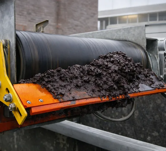
If the carrying side after the blade is already noticeably cleaner, but new material buildup continues to form beneath the cleaner, inspect the blade edge, receiving plate, and guide chute in sequence to identify where the carryback starts to accumulate or spill.
Focus on checking whether material accumulates at low points of the receiving plate, bends in the channel, and the outlet. Wet, sticky fines may gradually reduce the effective discharge cross-section, causing subsequently scraped material to accumulate again near the cleaner or spill over the edges of the channel.
After clearing or adjustment, observe the system again under similar feeding conditions to confirm that carryback can continuously enter the designated collection position and check whether new material buildup continues to form at the original accumulation points.
4. How to Balance Cleaning Performance and Conveyor Belt Service Life
Rubber conveyor belt cleaning needs to pay attention to changes in damage to the cover rubber, splices, and repaired areas, to determine whether cleaner contact is worsening local defects.
4.1 Control Blade Contact Condition and Applied Pressure
When the blade edge has local protrusions, chipping, or trapped hard particles, the applied force may become concentrated in a small contact area, increasing the risk of longitudinal scratches and localized loss of rubber thickness. In this case, the abnormal contact points need to be addressed first, and then the preload setting needs to be checked according to the equipment requirements.
The U.S. Bureau of Mines cleaning parameter test found that, under its test conditions, increasing the pressure beyond a certain level increased friction but did not further improve cleaning performance. Specific adjustments need to be based on the equipment requirements. The pressure values from the test cannot be directly used as universal settings.
After adjustment, both carryback changes and belt surface conditions need to be observed. If new longitudinal scratches appear, the corresponding blade edge needs to be checked against the lateral position of the scratches to confirm whether there are local protrusions, damage, or trapped foreign objects.
4.2 Check the Condition of the Cover Rubber and Splices
Vulcanized joints and repaired areas need to form a smooth transition with adjacent belt surfaces. Obvious steps, lifted edges, or loose edges may be repeatedly struck by the blade, causing existing damage to expand. These areas need to be assessed for repair first.
When the cover rubber has deep grooves, peeling, or exposed carcass, the need for repair or conveyor belt replacement needs to be determined based on the remaining rubber thickness, extent of damage, and splice condition. After repair, the contact condition between the repaired area and the blade also needs to be checked again.
When inspecting the cleaner, the supports and fasteners behind the blade also need to be checked. For designs where blade wear may cause these metal components to enter the belt surface contact area, the clearance between them and the belt surface needs to be checked to prevent metal from directly scratching the cover rubber.
4.3 Use Tools and Treatment Agents Compatible with the Belt
When manually removing stubborn adhered material after shutdown and isolation, scraping tools with smooth edges and suitable for the cover rubber need to be selected. Avoid scraping the rubber with sharp metal tools or removing accumulated material by prying at splice edges or repair edges, to prevent new damage.
If the belt surface has oil stains or special adhesive substances, the treatment agents used need to be checked for compatibility with the cover rubber, splice rubber, and repair materials. If suitability cannot be confirmed, the product composition and instructions for use need to be obtained first, and then we will check the treatment method based on the rubber compound type.
5. How to Evaluate Cleaning Performance During Continuous Operation
5.1 Evaluate Primary, Secondary, and Return Belt Cleaners Separately
When comparing cleaning performance, material conditions, belt speed, and conveying load need to be comparable. When evaluating an individual cleaner, the amount of residual material ahead of the blade also needs to be checked, to avoid attributing all changes resulting from the reduced load provided by the previous cleaner to improvements made by the subsequent cleaner.
Cleaning Device | Evaluation Location and Indicators | Basis for Assessment |
Primary conveyor belt cleaner | Residual material load and removal rate on the carrying side before and after the primary cleaner blade | Under similar residual material loads ahead of the blade, less material after the blade indicates improved primary cleaning performance; its cleaning target needs to match the remaining load handled by the secondary cleaner |
Secondary conveyor belt cleaner | Residual material load before and after the secondary cleaner blade, and the final residual material amount after the last cleaning stage | Under similar residual material loads ahead of the blade, less material after the blade indicates improved secondary cleaning performance; only when the residual material amount after the final cleaning blade does not exceed the agreed limit does the cleaning result on the carrying side meet the target |
Return belt cleaner | The pulley side after the cleaner, and material passing before entering the tail pulley | When material actually enters the cleaning area, if lumps that may cause damage when trapped still pass beyond the cleaner, the interception and protection target has not been achieved |
Residual material on the carrying side can be quantified by the residual material load per unit area:
Residual Material Load (g/m²) = Dry Mass of Residual Material (g) ÷ Corresponding Belt Surface Area (m²).
Before-and-after comparisons need to use the same sampling area and dry mass measurement method. Belt surface sampling should be carried out after shutdown and isolation, or by using an approved dedicated sampling method.
Specific acceptance limits need to correspond to clearly defined operating conditions and measurement points. A reduction in residual material load at the same measurement point indicates improved cleaning; only when it falls within the agreed limit does it indicate that the target has been achieved. Additional material buildup on the return run caused by this residual material can help verify the actual cleaning performance on the carrying side.
5.2 Evaluate Configuration Value Based on Cleaning Results and Maintenance Costs
After the cleaning results meet the target and belt protection requirements are satisfied, compare the costs required to maintain these results. The following indicators can be used:
Cost per Unit of Throughput = Total Labor Cleaning Costs, Wear Parts Costs, Related Repair Costs, and Verified Downtime Costs During the Same Period ÷ Throughput During the Same Period.
Cleaning and Protection Results | Costs | Assessment |
Target not achieved | Relatively low maintenance costs | Low costs cannot replace cleaning and protection requirements; the solution still does not meet operating requirements |
Target achieved | Additional maintenance costs are lower than the actual reductions in cleaning, repair, and downtime costs | The additional investment is economically justified |
Target achieved | A solution with comparable performance and reliability but lower overall costs is available | The current configuration is relatively less economical |
A solution with higher maintenance costs may also be suitable for wet, sticky, or highly abrasive operating conditions. To determine whether it is worthwhile, the overall costs of achieving the same cleaning target need to be compared, rather than drawing conclusions based only on blade prices, replacement frequency, or the number of manual cleaning operations.
6. Inspection and Maintenance of Cleaners Made from Different Materials (Conveyor Belt Cleaner Maintenance)
Blade inspection, cleaning, adjustment, and replacement must be carried out after shutdown, energy isolation, and lockout/tagout. Hazardous movement caused by gravity, tensioning devices, and stored elastic energy must be prevented according to site procedures.
6.1 Polyurethane Scraper Blades: Distinguishing Normal Wear from Material Damage
Polyurethane scraper blades need to be checked for both remaining usable height and blade edge integrity. When blade edge wear is relatively uniform, the scraper has no tears or permanent deformation, and remains within the allowable wear range, the compensation travel and preload setting can be checked according to the equipment requirements.
If the blade edge has tears, missing pieces, or permanent deformation that affects cleaning, the damaged scraper blade needs to be replaced. Preload adjustment cannot restore this damage or replace the need for replacement after the wear limit has been reached.
When installing a new scraper blade, the installation position and preload setting need to be checked again. The adjustment position of an old scraper blade near the end of its wear life cannot be directly used as the setting reference for a new blade.
6.2 Cemented Carbide Tips: Checking the Working Edges and Connections
Cemented carbide tips need to be checked mainly for edge wear, chipping, and the connection condition between the tips and the base. An intact base does not mean that the carbide working part still has sufficient usable material. Replacement decisions need to be based on the wear limit specified for that model.
When a tip is cracked, detached, or has a loose connection, the corresponding tip or blade assembly needs to be addressed or replaced. If a new tip is damaged again quickly at the same position, the source of impact needs to be checked against the splice, repair area, and contact position to avoid the same damage occurring again after repeated replacements.
For structures that allow individual section replacement, the contact positions of adjacent blades also need to be checked according to the model requirements to prevent excessive local force caused by height differences between new and old blades.
6.3 Ceramic Scraper Blocks: Checking Each Block for Damage and Connections
Ceramic blocks need to be inspected individually for cracks, chipped edges, missing pieces, and fixing conditions. Even if wear across the entire row of blocks is minor, individual cracked or loose blocks need to be addressed. Whether they can continue to be used cannot be judged solely by the overall remaining height.
For the steel wire rope-connected ceramic block structure mentioned earlier, the inspection also includes the connecting steel wire rope, end fasteners, and spring mechanism. (source:IDLERON )After removing accumulated material covering these areas, check whether the steel wire rope has broken strands or obvious wear, and whether the ends are loose.
Damage to ceramic blocks and abnormalities in connecting components need to be handled separately. After replacing the blocks, confirm that the connections are secure and the blocks are arranged as required, then restore the preload setting according to the requirements of that model.
7. Summary
To determine whether a rubber conveyor belt cleaning solution is suitable, first check whether it can achieve the targets of carryback control on the carrying side, material interception on the pulley side, and belt protection. If the targets have not been achieved, improvements should address the specific failure points. If the targets have been achieved, then compare the overall costs of wear parts, manual cleaning, repairs, and related downtime to determine whether the additional investment can bring corresponding benefits.
When cleaning performance is insufficient, low maintenance costs cannot prove that the configuration is suitable. When cleaning performance is stable, higher component costs may also be reasonable. Configuration decisions need to be based on actual cleaning results and operating benefits.
8. Frequently Asked Questions
8.1 Can compressed air be used to clean conveyor belts?
Yes. Compressed air can be used through air knives or nozzles to blow material off the belt surface, together with residual material collection and dust extraction equipment to direct the removed material to designated collection points and capture the dust generated by blowing. Under conditions involving silica-containing dust, particular attention is needed to verify dust capture effectiveness.
Before putting the equipment into service, check the residue on the belt surface, residual material collection, and dust monitoring results in the work area. If residual material spills or dust control is insufficient, adjust the nozzle position, airflow, and collection and dust extraction system; if site requirements still cannot be met, switch to scraper or brush cleaning.
8.2 Does adding a belt cleaner require cutting the conveyor belt?
Usually not. Belt cleaners are secured to the conveyor structure using brackets, and adding a cleaner generally does not involve cutting the belt body or remaking the splice, but the work still needs to be scheduled with the equipment shut down and isolated.
Some sites require additional mounting brackets, adjustments to chute openings, or additional channels for collecting residual material. When requesting a quotation, specify that the work involves retrofitting existing equipment and have the installation plan list the specific structural modifications and scope of work, to help determine whether installation can be completed within the scheduled maintenance window.
8.3 Are replacement blades interchangeable between belt cleaners for the same belt width?
This cannot be determined solely by conveyor belt width or blade length. Different models may use different retaining pins, mounting slots, bases, and blade cross-sections; even if the lengths are the same, they may not fit together correctly.
When purchasing replacement parts, provide the original belt cleaner model, blade part number, and dimensional drawings. For replacements across models or brands, confirm compatibility with the interface, working profile, and original tensioning mechanism; “it fits into place” cannot be the only basis for determining compatibility.
8.4 Can spare polyurethane scraper blades be stored for a long time?
The shelf life of polyurethane scraper blades and their service life after installation need to be managed separately. When purchasing, confirm the production date, batch, storage conditions, and allowable storage period; the same shelf life cannot be applied uniformly to different formulations.
Spare parts should be protected from light, kept under controlled temperatures, and properly supported according to product requirements to prevent deformation caused by prolonged pressure. When determining the purchase quantity, consider the expected consumption and replenishment cycle, use batches on a first-in, first-out basis, and reduce long-term stock accumulation.
8.5 Can belt cleaners remove rebar or bucket teeth mixed into the material?
No. Foreign objects such as rebar and bucket teeth need to be handled before they enter downstream equipment such as crushers; belt surface cleaners after discharge cannot be relied on to intercept them.
The feed conveyor belt can be equipped with a suspended permanent magnetic separator or an electromagnetic separator to attract and remove ferromagnetic foreign objects. For non-magnetic metals or large objects beyond the separator’s removal capacity, a metal detector can be configured to trigger a shutdown, followed by manual removal after shutdown and isolation; where suitable conditions are available, it can also be linked to an automatic rejection device to discharge them.