1. Overview of Sand Conveyor Belts: Engineering Attributes and Basic Positioning
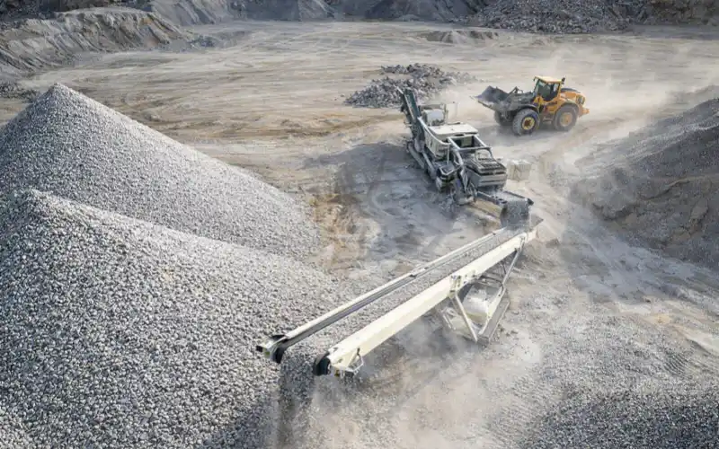
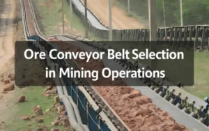
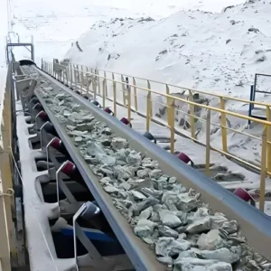
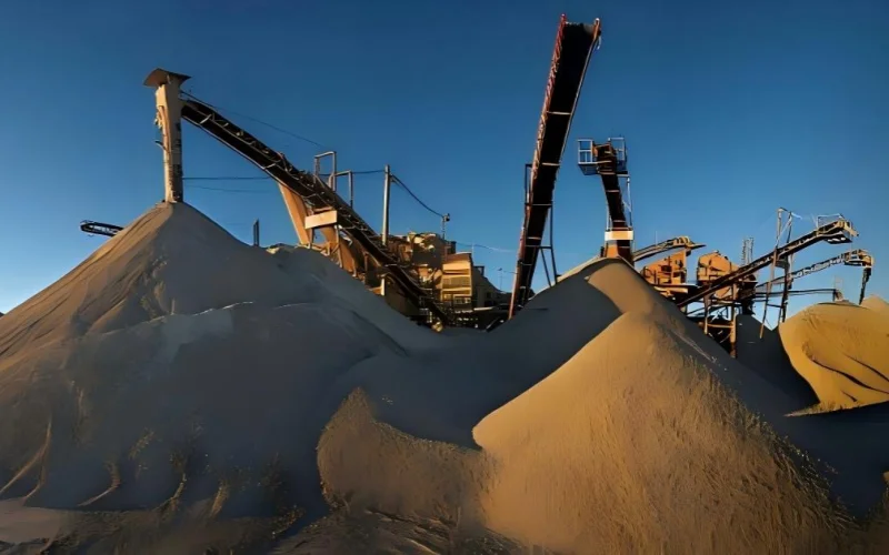
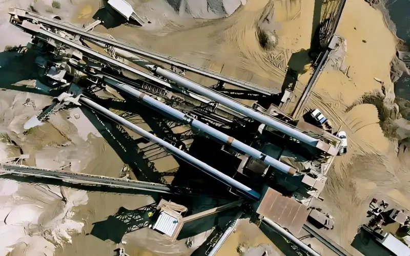
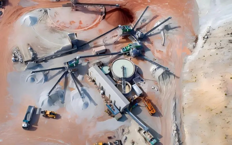
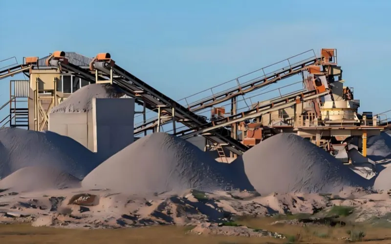
Sand conveyor belts are fundamental equipment used for the large-scale, continuous transportation of sand and gravel materials in sand production lines. Their core task is not simply “transportation,” but rather ensuring the stable operation of the entire production line. In any sand production system, sand conveyor belts are indispensable whenever materials need to be transferred between equipment.
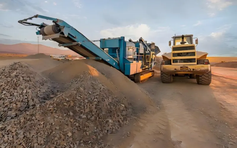
From a material perspective, sand conveyor belts primarily transport materials such as manufactured sand, natural sand, crushed stone, and ore. These materials have three typical characteristics: high abrasiveness, continuous impact, and large transport volume per unit time.
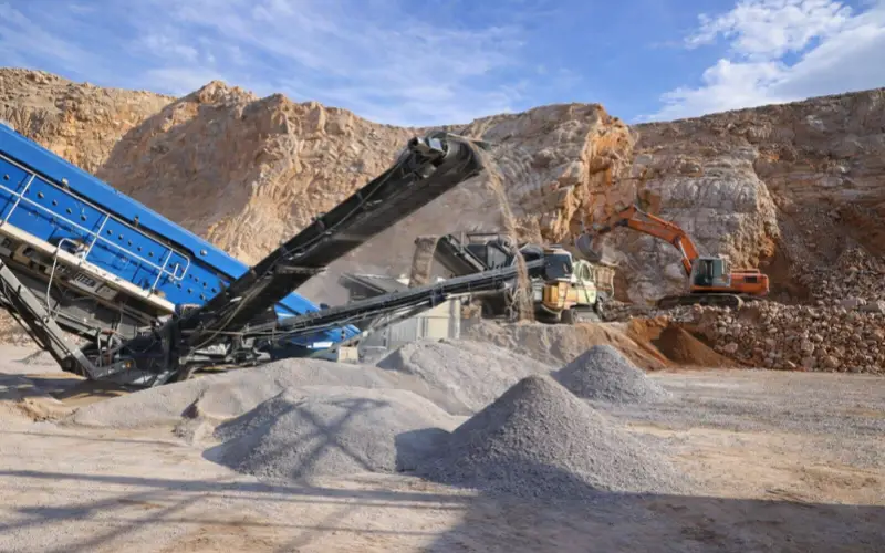
In sand production lines, sand conveyor belts typically connect vibrating feeders, crushing equipment, screening systems, and sand making machines, determining whether materials can flow continuously. If the conveyor belt performance is insufficient, excessive wear of the belt body will occur, directly reducing the overall production capacity of the line.
According to Wikipedia’s engineering description of conveyor belt systems, conveyor belt systems are key equipment for achieving large-scale production in the mining and aggregate industries, supporting stable transport capacities of hundreds to thousands of tons per hour.
In sand production lines, the wear resistance, impact-resistant structure, and operational stability of sand conveyor belts directly determine the actual service life of a single conveyor belt, the annual replacement frequency, and the comprehensive transportation cost per ton of sand.
2. The Core Role of Sand Conveyor Belts in Sand Production Lines
2.1 Sand conveyor belts determine the actual maximum conveying capacity of the sand production line.
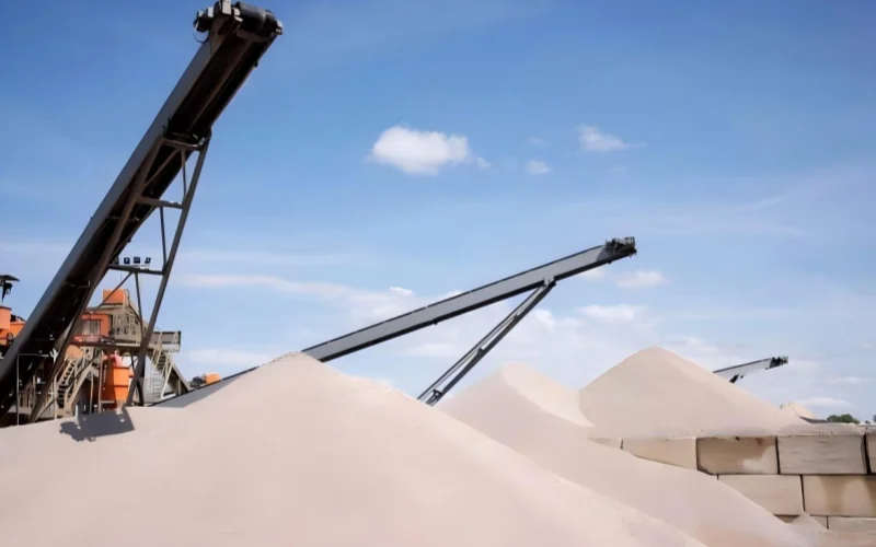
In a sand production line, the effective bandwidth, operating speed, and material accumulation height of the sand conveyor belt jointly determine the maximum throughput per unit time.
This throughput acts as a fixed upper limit in the system; other equipment can only operate within this limit.
When the design capacity of the crusher or sand making machine exceeds the conveying capacity of the conveyor belt, the following occurs:
- Feeding volume is passively reduced
- Downstream equipment experiences intermittent idling
- Actual output remains stable near the conveyor belt’s capacity
In this operating condition, the output is determined by the sand conveyor belt, not by the crushing or sand making equipment.
2.2 Sand conveyor belts bear a “continuous impact zone moving along the belt surface,” not a fixed material drop point.
During operation, the conveyor belt continuously cycles, and the material drop point constantly changes on the belt surface.
Therefore, the sand conveyor belt actually bears a moving impact zone, not a single fixed point.
This impact has the following characteristics:
- The impact position moves with the belt’s cycle
- High impact frequency and long duration
- Energy accumulates in the cover rubber and belt core in the form of fatigue
When the anti-impact structure is insufficient, the common results are:
- Accelerated wear of the cover rubber over an entire length
- Periodic fatigue damage to the belt core
- Overall decrease in interlayer bonding performance
This type of damage is cumulative failure, not instantaneous failure.
2.3 Sand conveyor belts are the “pre-signal source” in the interlocking system, not a single shutdown trigger point.
In most sand production lines, sand conveyor belts are equipped with:
- Belt misalignment switches
- Slippage or speed detection
- Material accumulation or blockage detection
These signals primarily affect the conveyor itself, rather than immediately interlocking the entire line to shut down.
In actual operation:
- Slight misalignment or early slippage are usually not visible to the naked eye
- The signals are first used for alarms or load reduction
- Only severe misalignment or continuous slippage will trigger the conveyor to shut down
Only when this conveyor is a critical material channel will upstream and downstream equipment be passively shut down due to lack of material or blockage. Therefore, abnormalities in the sand conveyor belt typically manifest as “single machine shutdowns” rather than a complete system collapse.
2.4 The operating status of the sand conveyor belt determines whether the abnormality is “controllable” or “passively spreading.”
In a sand production system, when the conveyor belt is operating properly:
- Slight deviations can be corrected by the idler rollers.
- Short-term slippage will not affect continuous material supply.
- Minor material accumulation will not spread to upstream or downstream equipment.
When the sand conveyor belt is improperly designed or selected:
- Small abnormalities are quickly amplified.
- Individual conveyors frequently shut down.
- Shutdowns affect upstream and downstream equipment in a cascading manner.
These problems are not equipment failures, but rather a result of insufficient system redundancy and stability.
In a sand production line, the sand conveyor belt, through its conveying capacity, fatigue-resistant structure, and operational stability, determines the production capacity limit, belt lifespan, and the frequency of shutdowns for individual conveyors. Whether the impact of a shutdown spreads depends on the system layout and redundancy design. Therefore, based on our experience over the past 20 years, we generally recommend that users or customers provide approximately 10% more redundancy within their budget for the specified TPH range.
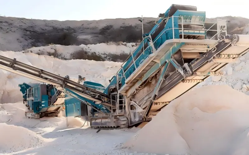
3. Engineering Constraints of Sand and Gravel Working Conditions on Conveying Systems
3.1 The high abrasiveness of sand and gravel materials constitutes a long-term structural constraint
Sand, crushed stone, and manufactured sand generally contain a high proportion of quartz particles, and their wear forms are mainly a superposition of sliding wear and rolling wear.
Under continuous operation conditions, wear is not a sudden local event, but rather a continuous accumulation along the conveying path.
The constraints this characteristic imposes on the conveying system include:
- The contact surface must allow for a predictable wear rate.
- Structural failure is primarily due to “life degradation,” not instantaneous failure.
- The system needs a long-term maintenance schedule, not frequent replacements.
This is the premise and background for the use of sand conveyor belts in sand and gravel scenarios, not the conclusion.
3.2 Impact in sand and gravel conveying is a fatigue load, not an instantaneous load
The impact generated during the transfer of sand and gravel comes from the superposition of continuous material dropping and speed differences.
The engineering characteristics of this impact are:
- Moderate impact amplitude
- High frequency of action
- Long duration
Therefore, the conveying system faces the problem of resisting long-term fatigue accumulation, not resisting a single impact.
Any structure that cannot disperse or absorb repeated loads will experience performance degradation during its operating cycle.
3.3 The load of sand and gravel conveying has continuous fluctuations
In actual operation, the particle size composition, moisture content, and instantaneous feed rate of sand and gravel continuously change.
This change does not occur in the form of a single extreme value, but rather in the form of frequent small fluctuations.
The constraints this imposes on the conveying system include:
- It must allow for short-term load deviations from the design value.
- The operating state cannot rely on precise, constant feeding.
- The system needs a certain degree of adaptability.
These fluctuation characteristics are the normal conditions of sand and gravel working conditions, not abnormal situations.
3.4 Sand and gravel conveying is based on the basic assumption of long-term continuous operation
Sand and gravel production usually uses daily continuous operation as the basic operating mode.
Under this mode, the constraints faced by the conveying system are:
- Downtime costs are higher than the cost of a single repair.
- Small faults are more destructive than large faults.
- Maintenance activities need to be integrated into the operating cycle, not interrupt the operation.
Therefore, the engineering design assumption of sand and gravel conveying systems is essentially “sustainable operation” rather than “performance limit.”
The working conditions involving sand and gravel impose structural constraints on the conveying system through abrasion, fatigue impact, load fluctuations, and long-term operation. The sand conveyor belt is defined and applied under these constraints, rather than existing as a single, isolated product.
4. Structural Composition and Operating Principles of Sand Conveyor Belt Systems
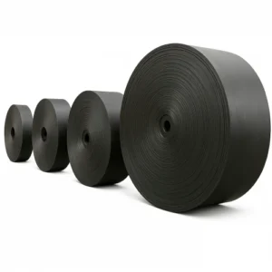
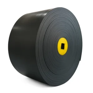
4.1 Sand Conveyor Belt Body
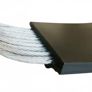
The conveyor belt body of a sand conveyor belt consists of a cover rubber, belt core, and edge rubber. This was previously discussed in my article on the Rubber Conveyor Belt Manufacturing Process and will not be repeated here. It is the component that directly contacts the material and circulates with the system.
- The top cover rubber lies on the belt surface, serving as the material contact layer and is typically thicker.
- The belt core resides in the middle layer, bearing tensile forces. It may consist of multiple layers, generally ranging from 2 to 6.
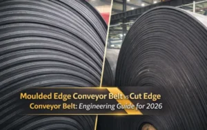
- Edge rubber protects the structural integrity of the belt sides but is not mandatory. Many customers also prefer edge-cut belts.
The belt body performs three fundamental functions within the system: carrying materials, transmitting tension, and participating in the continuous operation cycle.
4.2 Drive Unit and Speed Reduction System
The drive unit comprises a motor, speed reducer, and coupling, providing continuous power to the conveying system.
- The motor outputs rotational power.
- The speed reducer matches belt speed and torque requirements.
- Power is transmitted to the belt via the drive pulley.
The drive system maintains stable belt speed rather than directly controlling conveying volume.
4.3 Drive Pulley and Bend Pulley
The pulley system includes a drive pulley and multiple sets of bend pulleys.
- Drive pulley connects to the drive unit
- Bend pulleys alter the belt’s running direction
- Pulleys are covered with rubber or other coatings to increase friction
The pulley system transmits power and guides the conveyor belt along a closed-loop path.
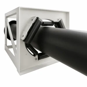
4.4 Idler System
Idlers are arranged along the conveying path to support the running belt.
- Upper idlers support the loading section
- Lower idlers support the return section
- Troughing idlers form the belt’s cross-sectional profile
Idlers fundamentally limit belt deflection and maintain stable running trajectory
4.5 Frame and Support Structure
The frame, constructed from structural steel or welded components, serves as the fixed foundation supporting the conveying system.
- Supports drive drums, idlers, and drive units
- Ensures geometric positioning of the conveying path
- Provides installation and maintenance access
While not directly involved in material transport, the frame determines the overall structural stability of the conveying system.
4.6 Tensioning Devices
Tensioning devices adjust the initial belt tension. Common types include:
- Screw tensioning
- Weight tensioning
- Hydraulic or automatic tensioning
The tensioning system maintains the required tension range during operation.
4.7 Safety and Auxiliary Devices
Sand conveyor belt systems typically incorporate auxiliary components such as:
- Deviation detection devices
- Speed or slip detection
- Scrapers
- Guard covers
These devices monitor operational status and fulfill on-site safety and maintenance requirements.
The sand conveyor belt system comprises the belt body, drive unit, drums, idlers, frame, tensioning system, and auxiliary devices. Each component performs distinct functions—load-bearing, power transmission, support, and monitoring—to form a complete continuous conveying system.
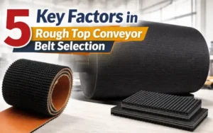
5. Common Sand Conveyor Belt Types (Engineering Judgment Based on Measurable Working Conditions)
In sand and gravel systems, the selection of the sand conveyor belt type must be based on “measurable working condition parameters.”
I will answer the following questions directly with clear data:
- What conveying distance is considered short? What distance is considered long?
- What sand and gravel particle size is considered medium? What size is considered large?
- What constitutes long-term continuous operation?
- When is it necessary to increase tensile strength?
- What DIN grade should be directly selected for the cover rubber?
5.1 Carcass Selection: Distance, Tension, and Structural Stability
5.1.1 Engineering Classification of Conveying Distance (by Single Conveyor)
In the sand and gravel industry, conveying distances are typically understood in engineering as follows:
- Short distance: ≤ 50 m
- Short to medium distance: 50–200 m
- Medium to long distance: 200–800 m
- Long distance: ≥ 800 m
Note: This refers to the effective conveying length of a single sand conveyor belt, not the cumulative length of the entire production line.
5.1.2 Applicable Range of EP Conveyor Belt
For short to medium distance sand and gravel conveying (50–200 m),
EP conveyor belts are the most common and stable choice.
Recommended engineering configuration:
- EP 3-ply / 4-ply
- Rated tensile strength: ≥ 400–630 N/mm
- Typical application bandwidth: 650 / 800 / 1000 / 1200 mm
Applicable conditions:
- Conveying distance ≤ 200 m
- Tension can be controlled by conventional tensioning devices
- Periodic maintenance is permissible on the production line
5.1.3 Medium to Long Distances and High Tension: When is a Steel Cord Conveyor Belt Required?
A steel cord conveyor belt should be considered when any of the following conditions are met:
- Single conveyor length ≥ 200–300 m
- Significant lifting height (large incline or high drop)
- Main trunk conveyor line; shutdown would affect the entire line
Common engineering grades:
- ST1000 / ST1250: Medium main conveyor
- ST1600 / ST2000: High-load main line
steel cord conveyor belt The significance lies not in being “more advanced,”
but in low elongation + high structural stability, used to control long-term tension changes.
5.2 Clear Definition of Sand and Gravel Particle Size and “Impact Grade”
5.2.1 Engineering Classification of Sand and Gravel Particle Size
In sand making and crushing systems, particle size is generally understood as follows:
- Fine: ≤ 10 mm (manufactured sand, fine sand)
- Medium: 10–40 mm (conventional crushed stone, undersize material)
- Large Particles/Blocks: ≥ 40–50 mm
- Large Blocks: ≥ 80–100 mm
When the proportion of ≥50 mm particles in the system exceeds 20–30%,it is generally considered an impact-type condition in engineering.
5.2.2 Typical Locations of Large Blocks
- Vibrating feeder → Primary crusher
- Primary crusher → Secondary crusher
These locations are the areas where sand conveyor belts are most prone to scratches, cracks, and premature failure.
5.3 Direct Selection Logic for Cover Rubber (using DIN grades as an example)
5.3.1 Conventional Sand and Gravel Conveying (Manufactured Sand, Conventional Crushed Stone)
Operating Conditions:
- Particle size ≤ 40 mm
- Ambient temperature
- Continuous operation, but with non-concentrated impact
Recommended Cover Rubber:
- DIN Y
- DIN abrasion ≤ 150 mm³
Applicable Locations:
- Post-screening conveying
- Finished sand conveying
- General branch lines
5.3.2 High-Abrasion Sand and Gravel Operating Conditions (High Quartz Content, Long Operating Time)
Operating Conditions:
- High-hardness materials such as quartz and basalt
- Daily operation ≥ 16–20 h
- Annual operation ≥ 300 days
Recommended Cover Rubber:
- DIN X
- DIN abrasion ≤ 120 mm³
This is the most commonly used “main conveying grade” in the sand and gravel industry.
5.3.3 Extremely High Abrasion/Impact Concentration Conditions
Conditions:
- High proportion of ≥ 50 mm block material
- Impact concentrated in fixed drop area
- High risk of surface scratches
Recommended cover rubber:
- DIN W
- DIN abrasion ≤ 90 mm³
Commonly used in:
- Feeding section
- Secondary crushing after primary crushing
- High drop transfer point
5.4 How much “high tensile strength” should be selected (specific to EP/ST)
5.4.1 Recommended tensile strength for EP conveyor belts
- Regular aggregate: EP 400 / EP 500 (3–4 ply)
- Impact-prone areas: EP 630 (4–5 ply)
When the number of EP layers is insufficient or the strength is low, the risk is not immediate belt breakage, but accelerated fatigue cracking.
5.4.2 Tensile Strength Rating of Steel Cord Conveyor Belts
- Medium Trunk Lines: ST1000–ST1250
- High Load/Long Distance: ST1600 and above
5.5 How to “Remedy” a Lower Tensile Strength Selection
This is a common and unavoidable situation in real-world projects.
When the tensile strength of a sand conveyor belt is low due to cost or delivery constraints, the risk can be mitigated by:
- Setting up an impact bed/impact idler
→ Dispersing the instantaneous impact of material drop
- Extending the length of the material drop buffer zone
→ Reducing the impact energy per unit area
- Controlling the material drop height ≤ 0–1.5 m
- Adjusting the chute structure to avoid concentrated impact points
These measures cannot replace proper belt selection, but they can significantly delay early belt damage.
6.Sand Conveyor Belt Specifications and Price Structure
In sand and gravel projects, the price of a sand conveyor belt is not a single number, but rather the result of multiple engineering parameters.
Discussing the price itself without breaking down these parameters is meaningless.
6.1 Core Specifications Determining Sand Conveyor Belt Prices
6.1.1 Belt Width
Belt width is the primary determinant of price because it directly determines:
- Adhesive consumption per meter
- Belt weight
- Transportation and installation costs
Common belt widths in sand and gravel systems include:
- 500 / 650 mm: Small branch lines, finished sand
- 800 / 1000 mm: Mainstream sand and gravel conveying
- 1200 / 1400 mm: High-capacity trunk lines
With other parameters remaining the same,
the price increases in steps with each increase in belt width, rather than linearly. It’s particularly important to note here that 2400mm is a watershed moment. Belts exceeding 2400mm are considered ultra-wide rubber conveyor belts, and prices increase dramatically beyond this width because vulcanizing machines exceeding 2400mm are very rare, requiring more stringent processing techniques.
6.1.2 Carcass Tensile Strength
Carcass strength directly determines the structural cost of a sand conveyor belt.
EP Conveyor Belt
Price is primarily affected by the following factors:
- Rated tensile strength (e.g., EP400 / EP500 / EP630): Higher requirements for EP fabric lead to a significant price increase.
- Ply number (3-ply / 4-ply / 5-ply): Increases processing steps and raw material costs.
In the sand and gravel industry:
- EP400 → EP500 → EP630 Each increase in grade significantly raises the cost per unit length, but simultaneously increases the tension safety margin.
Steel Cord Conveyor Belt
Pricing is primarily determined by:
- ST rating (ST1000 / ST1250 / ST1600 / ST2000)
- Steel cord usage and structural complexity, including the number of wires required for each steel cord core and the diameter of each core wire.
6.1.3 Cover Rubber Grade (DIN Grade)
The cover rubber is the most easily underestimated yet most directly impactful factor in the cost of sand conveyor belts.
Under the DIN standard:
- DIN Y
- DIN X
- DIN W
From Y → X → M, the cost increase stems from:
- Lower abrasion value (mm³)
- Higher raw material formulation costs
- Stricter quality control
Under the same carcass conditions,DIN W is significantly more expensive than DIN Y, while the improved lifespan is mainly seen in high-wear sections.
6.1.4 Cover Thickness
Cover thickness affects two things:
- Material cost per unit length/width
- Actual abrasion life
Common configurations:
- Top cover 6–8 mm / Bottom cover 2–3 mm (Regular gravel)
- Top cover ≥8 mm (High abrasion or impact applications)
Increasing thickness does not result in “greater strength,” but rather allows for a longer abrasion cycle.
6.1.5 Belt Length
Belt length has a limited impact on unit price, but a direct impact on the total price.
It’s important to note:
- Longer belt length usually means higher tensile strength.
- Higher tensile strength, in turn, increases the unit price.
Therefore, length often indirectly affects price through strength.
6.2 Price Structure Differences Under Different Sand and Gravel Working Conditions
6.2.1 Conventional Sand and Gravel Production Line (After Screening, Finished Sand)
Typical Configuration Combination:
- EP conveyor belt (EP400–EP500)
- DIN Y or DIN X cover
- Medium belt width (800–1000 mm)
Price Characteristics:
- Costs are concentrated in belt width and length
- Cover rubber cost is relatively controllable.
6.2.2 Main Conveyor Line (High Load, Long-Term Operation)
Typical Configuration Combination:
- EP630 or Steel Cord Conveyor Belt
- DIN X cover (DIN W in some sections)
- Larger belt width
Price Characteristics:
- Carcassstrength is the main cost factor
- Cover rubber grade has a significant impact on unit price.
6.2.3 Impact Concentration Section (Feeding Section, After Primary Crusher)
Typical Configuration Combination:
- High-strength EP conveyor belt (multiple ply)
- DIN W cover
- Thick top Cover
Price Characteristics:
- Unit price is significantly higher than ordinary conveyor belts
- However, the length is usually shorter, so the total price may not be the highest.
6.3 Why are “low-priced sand conveyor belts” often more expensive?
Common cost misjudgments in sand and gravel projects include:
- Using DIN Y cover rubber for high-wear mainlines
- Insufficient EP layers, relying on later additions of impact idlers as a remedy
- Reducing tensile strength to lower the initial purchase price
The direct results of these practices are usually:
- Shorter replacement cycles
- More frequent unplanned downtime
- Higher annualized conveying costs
The true cost of a sand conveyor belt is not “how much per meter,” but “how many times it needs to be replaced per year.”
6.4 Engineering Sequence for Price Evaluation
The correct order for evaluating sand conveyor belt quotes should be:
- Confirm operating conditions (distance, particle size, travel time)
- Secure carcass tensile strength
- Determine the DIN grade of the cover rubber
- Determine belt width and cover thickness
- Finally, compare prices
If the order is reversed, price comparison will lose its engineering significance.
7. Customized Configuration and Auxiliary Devices for Sand Conveyor Belts
In sand and gravel systems, the auxiliary devices for sand conveyor belts are not a case of “the more the better,” but rather whether they match the actual risk points of the operating conditions.
Whether the configuration is reasonable depends on one question:
Under the current operating conditions, will not configuring this device directly lead to loss of control over the conveyor belt’s lifespan or operational stability?
Based on this criterion, auxiliary devices can be divided into three categories.
7.1 Condition-Triggered Mandatory Configuration
When the following explicit operating conditions are met, the damage to the sand conveyor belt without configuration will be structural, rather than gradual.
7.1.1 Impact Idler / Impact Bed
Triggering Conditions (any one of these conditions is considered necessary):
- Particle drop height ≥ 5 m
- Particles ≥ 50 mm in the material account for ≥ 20%
- Particle drop is concentrated in a fixed area (feeding section, secondary crusher after primary crusher)
Direct Consequences of Not Having This Device:
- Local collapse or early cracking of the cover rubber
- Accelerated core fatigue, cracks propagate from the surface to the interior
- Actual lifespan is significantly lower than design expectations
Under the above conditions, the impact idler / impact bed is not a “protective feature,” but rather part of the load-bearing structure.
7.1.2 Skirt Rubber + Sealing System
Triggering Conditions:
- Drop width ≥ 7 × belt width
- Discrete material particle size distribution with a tendency for lateral diffusion
- Edge misalignment and material spillage have become common problems
Direct Consequences of Not Configuring:
- Continuous abnormal wear of the sand conveyor belt edge rubber
- Increased frequency of misalignment
- Actual damage is concentrated in non-load-bearing areas (premature edge failure)
7.2 Condition-Dependent Recommended Configuration
Whether to configure this depends on line length, downtime costs, and operational stability requirements. Not configuring it does not necessarily lead to immediate failure, but the risks can accumulate.
7.2.1 Belt Alignment Device
Recommended Configuration Conditions:
- Single conveyor length ≥ 150–200 m
- Multiple transfer points or non-linear layout
- Potential for foundation settlement or deviation
Explanation:
- The belt alignment device is used to suppress the spread of deviation.
- It cannot replace feed centering or idler roller installation accuracy.
7.2.2 Speed Switch / Slip Detection
Recommended Configuration Conditions:
- Main conveyor line
- A single sand conveyor belt stoppage will affect the entire line.
- Frequent start-stop cycles or significant load fluctuations.
Engineering Value:
- Early detection of slippage that is difficult to detect visually.
- Preventing localized overheating and the accumulation of hidden wear.
7.2.3 Belt Cleaner / Scraper
Recommended Configuration Conditions:
- Large moisture content fluctuations.
- High proportion of fine materials (≤10 mm) (High particle content)
- Significant material adhesion on the return journey
Typical risks of not configuring this feature:
- Secondary wear on the return journey
- Idler roller coating, abnormal resistance
- Increased causes of belt misalignment
7.3 Optimization and Retrofit Options
These features do not directly determine whether the sand conveyor belt “can run,” but rather whether it “runs more smoothly.”
7.3.1 Washing System
Applicable Scenarios:
- High mud content sand and gravel
- Systems with extremely high requirements for return journey cleaning
It is generally recommended to add this feature after the system has been running for a period of time, based on the actual material adhesion situation.
7.3.2 Enclosed Cover / Dust Hood
Applicable Scenarios:
- Strict environmental requirements
- Urban or factory projects
This feature primarily serves dust control and compliance, and has a limited impact on the mechanical life of the sand conveyor belt.
7.3.3 Sound & Light Alarm System
Applicable Scenarios:
- High degree of automation
- Nighttime or minimally staffed operation
An auxiliary configuration at the operation management level.
7.4 A Common but Incorrect Configuration Logic That Must Be Avoided
In sand and gravel projects, a common but incorrect practice is:
- Configuration is unrelated to operating conditions
- Using “multiple configurations” instead of “correct configurations”
The correct logic is:
- Impact problems → Solve impact problems first
- Deviation problems → Solve feeding and geometry problems first
- Abrasion problems → Solve covering adhesive and cleaning problems first
The essence of auxiliary devices is a risk control tool, not a stacking of functions.
8. Engineering Selection Logic of Sand Conveyor Belts
In the preceding sections, based on long-term engineering practice, the working characteristics, abrasion and impact risks, structural composition, and common configurations of sand conveyor belts in aggregate systems have been explained in layers. This content itself is not a conclusion, but rather the first layer of valid empirical judgment in the selection process.
The final selection of a sand conveyor belt is based on these engineering empirical judgments, through tension calculations, abrasion strength analysis, and verification of structural and installation conditions, gradually converging and ultimately confirming the result.
This process is not an opposition between experience and calculation, but rather a superposition and verification of both.
8.1 Essential Operating Parameters to be Defined Before Selection
Before determining the core structure, cover rubber grade, or auxiliary configurations, the following operating parameters must be defined and used as input conditions for engineering calculations and verification:
- Horizontal conveyor length L (m) and lifting height H (m)
- Conveyor path type (horizontal / inclined / large angle)
- Design conveyor capacity Q (t/h)
- Belt speed v (m/s) and belt width B (mm)
- Maximum particle size dₘₐₓ (mm) and proportion of particles ≥50 mm
- Material density ρ (t/m³)
- Start-up method and start-up coefficient Kₛ
- Ambient temperature and material temperature
- Annual operating days and daily operating hours
- Whether hot vulcanized splice conditions are available on site
These parameters correspond to the wear, impact, load fluctuation, and continuous operation assumptions discussed above. Without them, subsequent judgments cannot be verified in engineering.
8.2 Core Structure Confirmation: Working Tension as the Core Verification Principle
In engineering practice, conveyor distance is often used for empirical line stratification, but the final confirmation of the core structure must return to the maximum working tension.
The maximum working tension Tₘₐₓ is determined by the following factors:
- The combination of conveying length and lifting height (H/L)
- Material load and running resistance
- Starting conditions and starting coefficient
- Design safety factor
Based on this, the engineering validation logic for the core layer structure is as follows:
- When Tₘₐₓ ≤ 12–15% of the breaking strength of the EP conveyor belt,EP conveyor belts are within a reasonable structural utilization range.
- When Tₘₐₓ is higher, or when the system has specific requirements for low elongation and long-term tension stability,steel cord conveyor belts become the necessary choice.
Therefore, in specific projects:
- For a 200 m horizontal conveyor line, as long as the tension calculation meets the requirements,EP800 / 4-ply can still be considered a reasonable solution.
- For an 80 m steep incline conveyor line, when the lifting height is close to 50 m,even for shorter distances,working tension and elongation control may still require steel cords. Structure
The confirmation of the core layer type ultimately depends on the tension level and structural stability requirements, not the distance itself.
8.3 Verification Logic for Cover Adhesive DIN Grade: Abrasion Strength, Not Single Particle Size
The selection of the cover adhesive grade also requires engineering verification based on empirical layering.
In aggregate and gravel applications, key factors affecting abrasion intensity include:
- Material Mohs hardness
- Quartz sand: approx. 7
- Limestone, shale: approx. 3–4
- Belt speed (v): Under the same material conditions, increasing the belt speed from 2.5 m/s to 4.0 m/s significantly amplifies abrasion intensity.
- Daily operating time and annual operating cycle
- The influence of environmental and material temperature on rubber aging
- Material Mohs hardness
Under the combined effect of these factors, the typical verification logic for DIN cover rubber grades in engineering is as follows:
- DIN Y (≤150 mm³): Suitable for low-hardness materials, lower belt speeds, and conveyor sections with controlled abrasion intensity.
- DIN X (≤120 mm³): Suitable for high-hardness materials or main conveyor lines operating continuously for extended periods.
- DIN W (≤90 mm³): Used for conditions with combined high abrasion and high impact, such as quartz sand, high-speed main lines, or concentrated material drop areas.
Even with smaller particle sizes, the combination of high hardness, long operating times, and higher belt speeds will still drive the demand for higher cover rubber grades.
8.4 Complete Specification Confirmation of Steel Cord Conveyor Belt
In engineering selection of steel cord conveyor belts, simply specifying the ST rating is insufficient to constitute a complete specification.
Engineering confirmation must include at least the following information:
- ST rating (N/mm)
- Steel cord diameter d (mm)
- Cord construction (e.g., 3+9, 3+9+15)
Example specification:
ST1600 (5.4 / 3+9+15)
These parameters collectively determine the belt’s fatigue resistance, impact load capacity, and joint vulcanization quality.
8.5 Splice Conditions as Part of Selection Constraints
The splicing method directly affects the structural integrity and feasibility of the sand conveyor belt:
- EP conveyor belts can use cold bond or hot vulcanized splice.
- Steel cord conveyor belts typically require hot vulcanized splice in engineering to ensure joint efficiency.
If the availability of hot vulcanization conditions on site is not confirmed during the selection phase, the feasibility of the proposed solution will be directly affected.
8.6 Engineering Verification Logic of Impact Buffer Structures
Impact risk is not determined by a single drop height, but by the combined effects of the following factors:
- Maximum particle size and block material ratio
- Material density
- Drop height
- Belt speed and impact angle
- Whether the drop is concentrated in a fixed area
Based on this, the setting of the impact bed or impact idler should be based on impact energy and fatigue accumulation risk, rather than a fixed threshold.
9. Conclusion: Engineering Convergence Logic for Sand Conveyor Belt Selection
This paper does not focus on a single product, but rather establishes an engineering selection judgment system for sand conveyor belts in aggregate conveying systems. The core of this system lies not in the individual use of experience or parameters, but in the correspondence between measurable operating parameters and engineering verification logic.
In aggregate conveying systems, sand conveyor belt selection is first based on stratified operating conditions. Parameters such as conveying distance, lifting height, material particle size, and running time are not used to directly provide answers, but rather to define reasonable ranges for selection judgment. For example, different distance ranges (≤50 m, 50–200 m, ≥200 m) and particle size classifications (≤10 mm, 10–40 mm, ≥50 mm) determine the basic constraints of the system in terms of tension, impact, and abrasion.
Based on this, the selection conclusion must be confirmed through engineering verification logic.
The core layer structure is determined by the maximum working tension, not the conveying distance itself; the cover rubber grade is determined by abrasion strength, not simply by particle size; and the joint type and auxiliary configurations are constrained by actual operating conditions and site feasibility. The core of this process is: empirical stratification is used to define the scope, and calculation and verification are used to confirm its validity.
The selection of the cover rubber’s DIN grade is one of the most representative engineering decisions in this system. DIN Y, DIN X, and DIN W are not performance labels, but engineering standards corresponding to specific abrasion indicators (mm³), and their applicability must be judged comprehensively in conjunction with material hardness, belt speed, and operating time. Similarly, the distinction between EP conveyor belts and steel cord conveyor belts is not an empirical opposition of “short-distance or long-distance,” but rather based on calculations of tension utilization and structural stability.
Price structure and auxiliary configurations are not independent decision items in this system. Bandwidth, core strength, cover rubber grade, and cover thickness determine the structural cost of a sand conveyor belt. Auxiliary configurations such as impact beds, belt alignment devices, and cleaning systems intervene through conditional triggering logic to address identified risks of impact, belt misalignment, or material adhesion. The engineering significance of these configurations lies in their compatibility with the confirmed operating constraints, rather than the sheer number of configurations.
Therefore, once the operating parameters are fully defined and validated through tension, abrasion, and structural conditions, the selection of a sand conveyor belt becomes engineering deterministic.
Under this determinism, the conveyor belt is no longer a potential source of risk, but rather a system component operating stably within its design boundaries.
10.FAQs
FAQ 1: Why do sand conveyor belts have such different lifespans in different projects?
Because lifespan isn’t solely determined by materials or brand, but by whether operational limits are consistently exceeded.
Even with a high-grade rubber cover, if it’s consistently subjected to tensions exceeding design limits, concentrated impacts, or insufficient cleaning, the actual wear rate will be magnified exponentially. Lifespan differences essentially reflect the degree of operational condition matching, not the “quality” of the product itself.
FAQ 2: If the designed capacity is frequently not reached, should a wider conveyor belt be used first?
Not necessarily.
In many projects, the limiting factor for capacity isn’t belt width, but rather belt speed, material layer height, or tension margin.
Blindly widening the belt will lead to higher belt weight and tension requirements, potentially accelerating fatigue. The correct order should be: first determine if the current belt allows for increased belt speed or material layer height, then consider geometric adjustments.
FAQ 3: Material particle size fluctuates greatly during actual operation; should the maximum or average value be used when selecting a conveyor belt?
The “destructive particle size” ,not the “average particle size”, should be used as the criterion. Small but persistent occurrences of large material pieces often determine impact and fatigue levels. If particles ≥50 mm or ≥80 mm in diameter repeatedly appear during operation, even if the proportion is low, it needs to be reflected in the structural and cushioning design.
FAQ 4: What are the effects of increasing belt speed on sand conveyor belts besides wear?
Besides wear, increasing belt speed significantly affects three aspects:
- Impact angle and energy distribution
- Material projection tendency and risk of material sticking on the return stroke
- Dynamic stress fluctuations at the joint
Therefore, increasing belt speed is essentially a system-level adjustment, not a single efficiency optimization method.
FAQ 5: Why do some conveyor belts always experience problems first at the joint?
Because the joint is where structural continuity is broken.
If the joint type, vulcanization quality, or joint length does not match the actual tension level, the joint will experience higher stress concentration than the belt body. Many “belt quality problems” ultimately trace back to a mismatch between joint design and operating conditions.
FAQ 6: Can adding an impact bed compensate for the problem of an under-selected conveyor belt?
Impact beds can only partially alleviate, not replace, damage.
They can reduce instantaneous impact, but cannot change long-term tension levels or wear resistance. If the belt strength or cover grade is insufficient, an impact bed can only delay the onset of damage, not fundamentally solve the problem.
FAQ 7: Why do some projects run stably initially, only to experience a sudden surge of problems after six months?
This is a typical example of the cumulative effect of fatigue and wear.
Sand conveyor belts operating near design limits often perform normally initially, but as the cover thins, the belt elongates, and joint efficiency decreases, the system margin is rapidly depleted, and problems manifest rapidly within a short period.
FAQ 8: If a high DIN grade has already been selected, is it still necessary to pay attention to cover thickness?
Yes, and the two have different functions.
The DIN grade determines the unit wear rate, while the cover thickness determines the total amount of wear that can be tolerated.
In high-wear but space-constrained conditions, a thin, high-grade cover may not be as practical as a reasonably thick, medium-to-high-grade cover.
FAQ 9: Why should the configuration of sand conveyor belts differ in different sections of the same line?
Because the types of risks are different.
The feeding section mainly bears impact, the main line bears tension and continuous wear, and the return section faces material adhesion and secondary wear.
A uniform configuration often means insufficient in critical sections and waste in non-critical sections.
FAQ 10: How to determine if an existing sand conveyor belt is already in a “structural critical state”?
You can start with three signals:
- A significant increase in belt elongation compensation frequency
- A higher wear rate at joints or in localized areas than in other sections
- A significant increase in reliance on auxiliary devices such as belt alignment and cleaning during operation
These signals usually appear before obvious faults and are important criteria for determining whether a re-evaluation and re-selection is necessary.