1.What is a Sidewall Conveyor Belt & Why It Exists
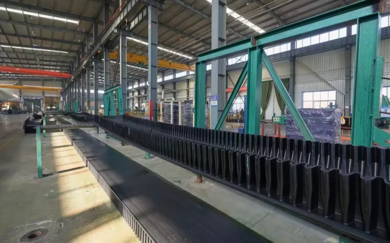
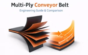
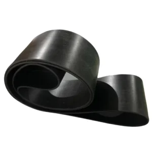
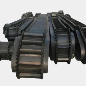
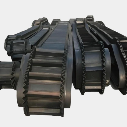
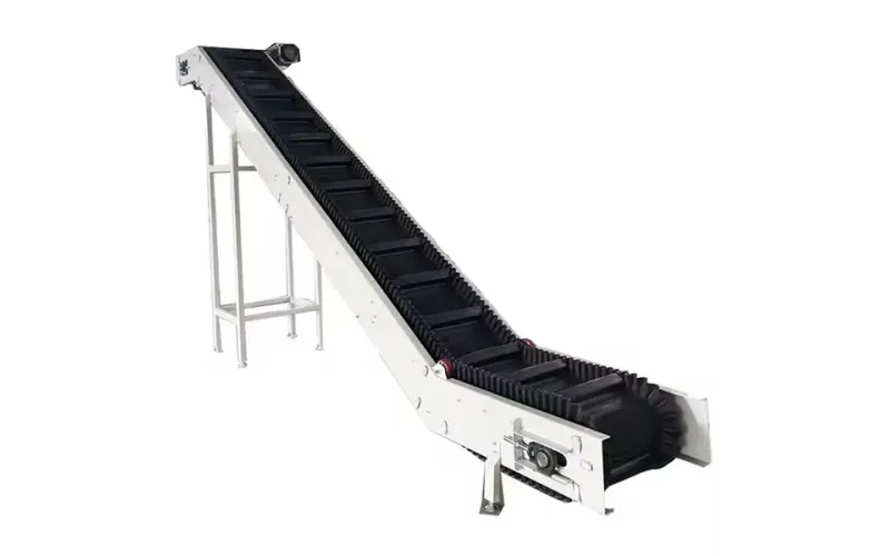
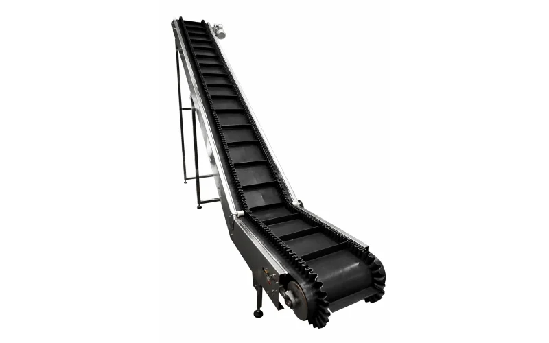
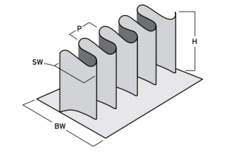
From a manufacturing and engineering perspective, a sidewall conveyor belt is an integral conveyor belt structure used for high-incline and vertical conveying. It consists of three core units: a base belt, a corrugated sidewall, and cleats. Its design goal is to achieve continuous conveying at large angles on a single conveyor line.
In engineering calculations, the effective conveying angle of a standard flat belt is typically limited by the coefficient of friction between the material and the cover rubber. For most bulk material handling conditions, when the angle exceeds 18°–22°, even increasing the friction rating of the cover rubber cannot prevent material rollback. This is determined by both the component of gravity and the friction limit, not by installation or tensioning issues.
The essential difference between a sidewall conveyor belt and a flat belt is that it no longer relies on friction to maintain the material’s position. Instead, it uses the sidewall and cleats to form independent load-bearing units, thus geometrically restricting the material’s displacement. This structural constraint allows the conveying angle to be increased from 35° to 90°, depending on cleat height, spacing, and material bulk density.
In practical engineering solutions, we typically see three alternative paths:
- Increasing the number of flat belts and employing a multi-stage conveyor system
- Using a bucket elevator for vertical lifting
- Using a sidewall rubber conveyor belt for single-line lifting
The common problem with the first two solutions is that:
The increased number of transfer points leads to a simultaneous increase in system complexity and maintenance costs; simultaneously, the risk of material breakage and dust leakage significantly increases.
This is the fundamental reason why conveyor belts with sidewalls have become a mature solution—it solves the height problem through structural integration, rather than system fragmentation.
Tiantie’s manufacturing conclusion: The value of a sidewall conveyor belt lies not in “how high it can climb,” but in achieving the desired height transport with the fewest possible conveying units within a limited space.
From a long-term operational perspective, reducing transfer points often improves system stability more than increasing individual machine parameters. This design logic is also consistent with the system simplification principle of ISO conveyor system engineering.
2.How Sidewall Conveyor Belts Handle Steep and Vertical Transport
From an engineering perspective, the core reason why sidewall conveyor belts can achieve large-angle and even near-vertical conveying is not due to increased friction, but rather to the structural reconstruction of the material’s force path.
In sidewall conveyor belts, the material no longer primarily adheres to the belt surface, but is carried by cleats and the load is transferred through the base belt. This transforms the system from friction-controlled conveying to geometry-controlled conveying.
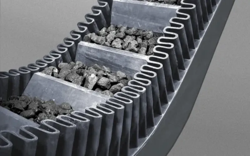
2.1 How Sidewall + Cleats Form a Stable Conveying Chamber During Operation
In actual operation, the corrugated sidewall and cleats together form a continuous pocket structure:
- The corrugated sidewall is responsible for limiting the lateral spread of material.
- The cleats bear the component of gravity along the conveying direction.
- The base belt provides overall tensile strength and operational stability.
Each pocket can be understood as a continuously moving load-bearing unit. Material stability no longer depends on surface friction, but rather on cleat geometry, spacing, and pocket filling ratio.
This is the engineering basis for Sidewall Conveyor Belts’ ability to perform large-angle lifting on a single conveyor line.

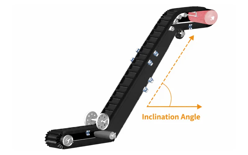
2.2 Why Sidewall Conveyor Belts Can Be Used for High Inclination Angle Conveying
As the incline angle increases, the primary failure mode of a conventional flat belt is material rollback.
However, in a Sidewall Conveyor Belt system, design concerns shift to the following variables:
- Is the cleat height sufficient to bear the material load?
- Is the fatigue stress of the cleat root controllable?
- Does the base belt stiffness match the pulley diameter?
- The filling stability of the pocket during operation.
In engineering practice, we typically understand the feasible range as:
- 35°–45°: Most bulk materials can operate stably.
- 45°–80°: Sidewall conveyor belts can still be used, but structural design must be more cautious.
- >80°: As a rational technical recommendation for the plant, bucket elevator belt options should be evaluated simultaneously.
It is important to emphasize that:
Under conditions >80°, it is not that Sidewall conveyor belts “cannot work,” but rather that from the perspective of long-term reliability and maintenance predictability, bucket structures are often more stable.
2.3 Engineering Trade-offs Between Sidewall Conveyor Belts and Bucket Elevator Belts
In systems requiring continuous conveying, fewer transfer points, and encompassing both horizontal and vertical sections, sidewall conveyor belts still offer significant system advantages.
However, when the design inclination angle enters the extreme range (typically >80°), we tend to include bucket elevator belts in the comparison rather than simply increasing the cleat and sidewall dimensions of the sidewall conveyor belt.
This trade-off is not based on theoretical judgment, but rather on a comprehensive assessment of fatigue behavior and maintenance costs during long-term operation.
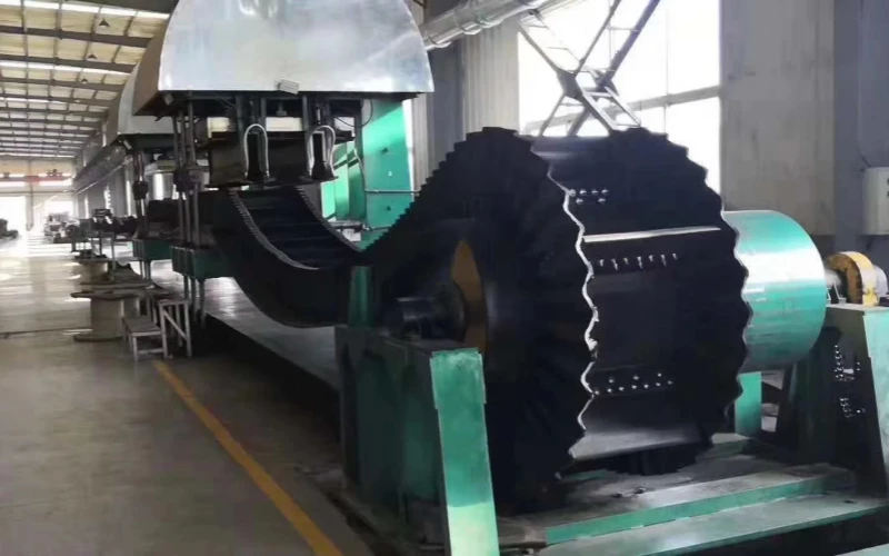
3.Core Components from a Manufacturer’s View — Sidewall Conveyor Belt
A sidewall conveyor belt is a system product comprised of multiple components, including the base belt, sidewall, and cleat, which collectively determine its performance and lifespan.
Pricing and communicating for this type of product involves more complex structural parameters, requiring more time and patience.
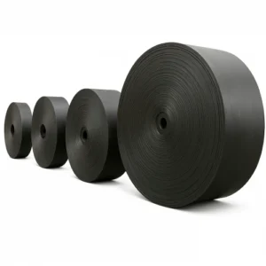
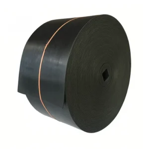
3.1 The Base Belt as the Structural Foundation
In sidewall conveyor belts, the base belt is the ultimate load-bearing foundation. Its core function is not only tensile strength but also providing a stable and repeatable operating platform for the sidewall and cleat.
From a manufacturing and pricing perspective, the base belt requires at least the following parameters to be clearly defined:
- Base belt width
- Base belt thickness
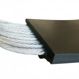
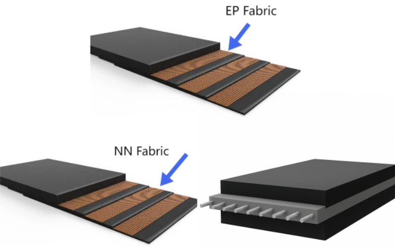
- Carcass type (e.g., EP/NN/steel cord)
- Number of plies
These parameters determine the base belt’s strength rating, bending characteristics, and compatibility with the pulley, forming the basis for all subsequent structural design.

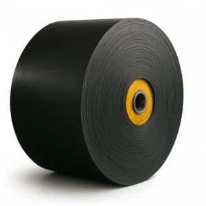
3.2 Sidewalls as an Assembled Structural Element
In a sidewall conveyor belt, the sidewall is not simply an attachment to the base belt edge, but a structural component with a clearly defined assembly location and dimensions.
In manufacturing and pricing, the sidewall must be quantified separately as:
- Sidewall height
- Sidewall width
The sidewall height determines the effective volume of the pocket; the sidewall width directly affects its stability during operation, fatigue characteristics, and the reliability of its adhesion to the base belt.
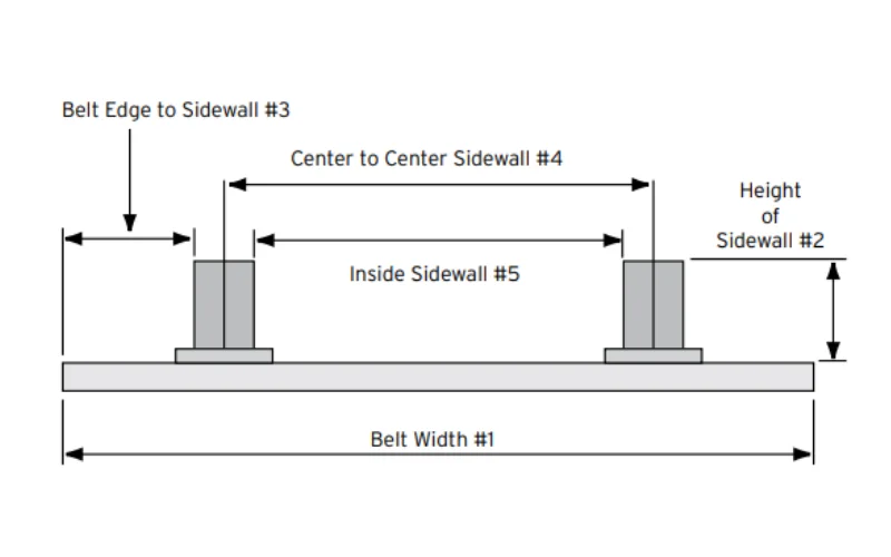
More importantly, the sidewall is not assembled at the outermost edge of the base belt, but rather recessed inwards before bonding. This assembly relationship introduces a parameter that must be understood holistically—the empty margin.

3.3 Empty Margin as a Geometric Relationship, Not a Standalone Feature
In the structural parameters of a sidewall conveyor belt, the empty margin refers to the distance between the outside edge of the sidewall and the physical edge of the base belt.
It is important to emphasize that the clearance is not an attribute of a specific component, but rather a result of the assembly relationship between the sidewall and the base belt.
It is determined by the following factors:
- Base belt width
- Sidewall width
- Sidewall bonding position
Whether this distance is reasonable directly affects:
- Whether the sidewall has sufficient space for expansion and deformation in the pulley area
- The shear stress level of the bonded area during multi-directional movement
- The long-term fatigue performance of the entire Sidewall conveyor belt during turning and return strokes
Therefore, the clearance is not a performance selling point, but rather an engineering geometry condition that must be confirmed.

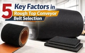
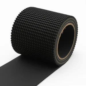
3.4 Cleats That Define Carrying Capacity
In Sidewall conveyor belts, the cleat is a structural component that directly determines the conveying capacity and stability, not simply a material stop.
From a manufacturing and selection perspective, a cleat needs to be clearly defined as a combination of the following parameters:
- Cleat height
- Cleat width
- Cleat spacing
These three parameters together determine:
- The effective load-bearing capacity of a single pocket
- Whether material falls back at high angles
- The long-term stress state of the cleat root and base belt
Especially in the 45–80° application range, matching the cleat spacing with the material flow rate is more critical than simply increasing the cleat height.

3.5 Why These Parameters Are Required for Quotation
From a factory perspective, a valid quote cannot be provided for a Sidewall Conveyor Belt without complete structural parameters.
An executable and reproducible quote requires at least the following data:
- Sidewall height
- Sidewall width
- Cleat height
- Cleat width
- Cleat spacing
- Base belt width
- Base belt thickness
- Carcass type
- Number of plies
- Empty margin
These parameters are not intended to increase communication costs, but rather to ensure that:
- The quote corresponds to the actual manufacturing structure
- The design is manufacturable
- Subsequent performance and service life are predictable
If any of these are missing, the quote is merely a reference price, not an engineering solution.

4.Why Sidewall Conveyor Belts Are Chosen in Real Projects
In real-world projects, the choice of sidewall conveyor belts is usually not based on feasibility, but rather on unavoidable system-level constraints. These projects are often locked in by several conditions during the design phase.
4.1 Space Is the First and Strongest Constraint
In many projects, available space is the first factor to lock in the choice of solution.
When the site is already occupied by building structures, steel platforms, or existing equipment, multi-segment flat belt systems often become infeasible during the layout phase:
- The conveyor length cannot be extended.
- Transfer points cannot be placed.
- Height changes are forced to be split into multiple stages.
Under these circumstances, the value of sidewall conveyor belts is not performance advantage, but rather the ability to achieve height changes within a limited space.
Whether it is “more economical” is often a secondary consideration.
4.2 Material Characteristics Decide Whether Transfers Are Acceptable
During the solution comparison phase, material behavior quickly eliminates some conveyor methods.
For the following material characteristics, multiple transfers are inherently a source of risk:
- Uneven particle size distribution
- Sensitive to breakage
- High powder content, prone to dust generation
- Poor flowability, prone to accumulation
When materials are unsuitable for repeated feeding and re-acceleration, a continuous conveying path is more important than the equipment type itself.
Sidewall conveyor belts are used in these types of projects because they reduce the number of unavoidable material interventions.
4.3 Required Lift Height Locks the System Type
Once the required lifting height is determined, the choice of solution often converges rapidly.
When the height requirement exceeds the reasonable range of a single flat belt, and it is desirable to avoid complex multi-stage systems, the number of feasible solutions decreases significantly.
In the lifting ranges of 35–45° and 45–80°, sidewall conveyor belts are often one of the few solutions that can be both deployed and operated continuously.
Only when the design angle approaches 80° or higher will we simultaneously evaluate the bucket elevator solution at the engineering level. This is based on structural compatibility, not a rejection of the sidewall conveyor belt’s capabilities.
4.4 Engineering Validation Comes After the Choice Is Made
Only when space, materials, and lifting height point to Sidewall conveyor belts will the engineering team proceed to verify:
- Whether the corresponding structural parameters are manufacturable
- Whether the parameters are suitable for material handling
- Whether the service life meets expectations
These questions are not the starting point for driving customer selection, but rather necessary steps to ensure that the choice will not be overturned during the operational phase.
5.What Materials Can Be Conveyed Reliably
In project selection, the suitability of Sidewall conveyor belts is primarily determined by the materials, not the equipment’s capabilities.
From a manufacturing and engineering perspective, the judgment criteria are not complex; the key lies in the actual behavior of the materials within the pocket structure.
5.1 Bulk Materials That Work Well with Sidewall Conveyor Belts
The operational stability of Sidewall conveyor belts is predictable for the following material types:
- Free-flowing bulk materials (e.g., coal, ore, sand, fertilizer)
- Moderate particle size distribution (no large amounts of oversized lumps or extremely fine powder)
- Stable bulk density, not drastically changing with moisture content
The stress state of these materials within the pocket is clear:
- Gravity is supported by the cleat
- Lateral diffusion is limited by the sidewall
- The material itself does not exert abnormal lateral pressure on the sidewall
These materials exhibit a typical “natural fit” within the 35–45° and 45–80° ranges.
5.2 Fine and Powdery Materials: Usually Acceptable, With Conditions
Powder and fine particulate materials are not unusable, but the following conditions must be met:
- The material must not have strong adhesive properties.
- It must not form bridging or adhesive layers within the pocket.
- Cleat spacing and filling ratio must be controlled.
In actual engineering, powder materials are more likely to expose design problems than equipment problems:
- Excessive clean spacing → slippage
- Overfilling of the pocket → abnormal sidewall pressure
- Improperly designed discharge area → residue accumulation
Sidewall conveyor belts can reliably transport powder materials as long as these conditions are correctly defined, but they have a lower tolerance for design errors.
5.3 Irregular and Lump Materials: Need Careful Evaluation
The use of Sidewall Conveyor Belts requires careful evaluation for the following materials:
- Large lump materials
- Irregular shapes with sharp edges
- Mixed size distribution with wide spread
The problem with these materials is not whether they can be conveyed, but rather:
- Whether they will create concentrated lateral pressure on the sidewall
- Whether they will form unstable accumulations within the pocket
- Whether they will cause jamming during discharge
In the 45–80° range, lump material is often the main cause of sidewall fatigue.
If the material size is close to or exceeds the cleat height, the system risk increases significantly.
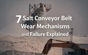
5.4 Materials That Are Usually Not a Good Fit
We generally do not recommend prioritizing Sidewall Conveyor Belts in the following situations:
- Highly sticky materials (wet sludge, strongly adhesive materials)
- Materials that smear or cake on the sidewall surface
- Extreme temperature materials not matched with a corresponding rubber compound
These problems cannot be solved by simply enlarging the sidewall or cleat; in fact, they will accelerate failure.
When the design angle is close to 80° or higher, even if the material itself is controllable, we will prioritize evaluating a bucket elevator solution because it is less dependent on material behavior.
5.5 Material Behavior Is More Important Than Industry Labels
During the selection phase, we focus more on:
- Whether the material is predictable within the pocket
- Whether it will continuously apply abnormal lateral loads
- Whether the discharge behavior is controllable
rather than whether it belongs to “mining,” “building materials,” or “chemicals.”
This is why Sidewall Conveyor Belts operate stably in some mining projects but experience frequent problems in some chemical projects—the deciding factor is always the material behavior, not the industry name.
6.Industries Where Sidewall Conveyor Belts Are Commonly Used
Sidewall conveyor belts are naturally required in certain industries due to process conditions that necessitate high-angle conveying.
The following breakdown by industry explains the sources of these constraints.
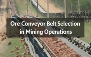
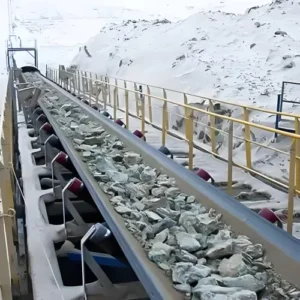
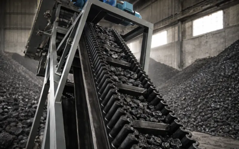
6.1 Mining and Quarry Operations
In mining and quarry systems, high-angle conveying typically arises from two unavoidable conditions:
- Difference between pit depth and plant elevation
- Limited available horizontal distance
When there is a significant height difference between the mining area and the crushing, screening, or stockpiling system, extending the horizontal conveyor line often means:
- Extensive civil engineering work
- Longer conveyor routes
- Multiple transfer points
In the 35–80° range, sidewall conveyor belts can achieve continuous lifting in limited space, reducing system length and transfer points, which is the core reason for their adoption in this scenario.
6.2 Cement and Construction Material Plants
The demand for high-angle conveying in the cement and construction materials industry stems more from plant layout than from the capabilities of individual equipment.
Typical scenarios include:
- Transporting raw materials from ground level to preheaters or silos
- Conveying finished or semi-finished products between multi-story structures
In these types of plants, equipment is usually “stacked,” with concentrated height changes and limited space.
Sidewall conveyor belts are chosen because:
They can directly complete cross-floor conveying without adding multiple transfer points.
6.3 Power Generation and Heavy Industry
In power generation and heavy industry projects, high-angle conveying is often associated with the following conditions:
- Transporting fuel or raw materials from the unloading area to high-level storage silos
- Continuous system operation, highly sensitive to interruptions and transfer points
In these systems, multi-segment conveying not only increases maintenance points but also introduces more potential downtime risks.
Therefore, in the 35–80° range, sidewall conveyor belts are often used to compress the length of the conveying path, rather than simply increasing the angle.
6.4 Recycling and Waste Handling Systems
The need for high-angle conveying in recycling and waste handling systems usually comes from two aspects:
- Limited height space at the site
- Complex material forms, unsuitable for multiple transfers
In these systems, the lifting height is often concentrated between the sorting line and the storage unit. By reducing transfer points, sidewall conveyor belts can lower the risk of material spillage, accumulation, and jamming, which is more important than the ability to climb inclines itself.
6.5 Agriculture and Chemical Processing
In agricultural and chemical systems, high-angle conveying is more related to process integration:
- Raw materials or finished products move vertically between different processes.
- The goal is to reduce intermediate buffering and manual intervention.
When material characteristics allow for continuous conveying, sidewall conveyor belts provide a way to integrate multiple process stages vertically within a limited space.
However, this solution requires careful evaluation when the material is viscous or its behavior is unpredictable.
7.Typical Conveyor Layouts We See in Practice
In practical projects, sidewall conveyor belts require the selection of an appropriate layout based on the actual scenario.
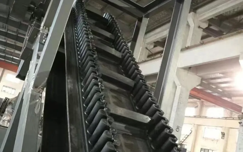
7.1 Straight Incline Layout
This is the most basic and often underestimated layout.
Applicable conditions:
- Clear lifting height
- Single conveying direction
- Stable inclination angle of 35–45° or 45–80°
In this layout, the function of the sidewall conveyor belt is very direct:
To achieve height elevation within a limited length without introducing additional transfer points.
Engineering considerations:
- Does the loading area provide sufficient distance for material sorting and acceleration?
- Does the incline starting section prevent material from entering the high inclination angle before stabilization?
Common problems:
- The entrance section is too short, causing material to accumulate in front of the cleats.
- Cleat spacing does not match the flow rate.
7.2 Near-Vertical Lift Layout
When space constraints become even tighter, the layout is pushed towards a near-vertical form.
Typical characteristics:
- Concentrated lifting height
- Extremely limited horizontal distance
- Inclination angle close to 80°
From a manufacturer’s perspective, this type of layout is technically feasible, but the tolerance for error is significantly reduced.
Common misjudgments:
- Attempting to “force the angle” by infinitely increasing the cleat height
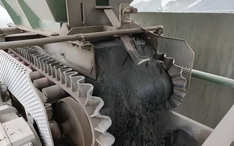
- Ignoring the material discharge behavior in the discharge area
In this angle range, we usually evaluate bucket elevator solutions simultaneously during the design phase, not because the sidewall structure fails, but because the long-term behavior of the bucket system at extreme angles is more predictable.
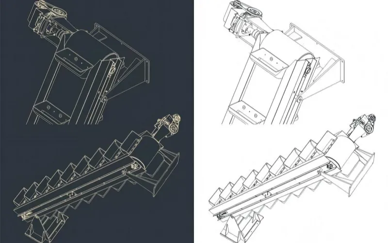
7.3 Z-Type Layout
The Z-type is the most common and engineering-wise the most mature complex layout form for sidewall conveyor belts.
Its structural characteristics are very clear:
- horizontal → incline → horizontal
- The conveying direction only changes once in the vertical plane
- No reverse bending is introduced
The core value of the Z-type lies in system integration:
- Bottom material feeding
- Mid-section lifting
- Direct conveying or unloading at the top
The real engineering challenges are not in the inclination angle, but in the two transition zones:
- loading → incline
- incline → discharge
Common mistakes:
- Insufficient transition radius
- Sidewall is forced to deform rapidly at the turning point
- Ignoring the stability of the material in the turning area
Among all complex layouts, the Z-type has the highest success rate, provided that the transition sections are treated as key design objects, not simply connecting sections.

7.4 L-Type Layout
L-type layouts are commonly found in existing plant retrofit projects.
Applicable Scenarios:
- Existing structures do not allow for a straight layout.
- A change of direction must be completed within a short distance.
In this layout, the problem is not whether or not there is a bend, but rather:
- Whether the turning point creates stress concentration.
- Whether the sidewall and base belt are forced to deform synchronously.
Common Mistakes:
- Treating the L-type layout as a “straight line + elbow”.
- Ignoring the fatigue accumulation in the sidewall at the turning area.
The long-term operation of an L-type layout depends on the controlled design of the turning point, not on simply increasing structural strength.
8.How We Approach Sidewall Conveyor Belt Selection
The selection of a sidewall conveyor belt has a clear and fixed starting point.
The first step is always to determine the geometry of the operating conditions.
Step 1: Determine the Actual Operating Inclination Angle
The first step in selection is to do only one thing: confirm the actual operating inclination angle range of the conveyor system.
- 35–45°: The focus is on shortening the conveyor length and reducing transfer points.
- 45–80°: The cleat becomes the main load-bearing structure, and the structural matching requirements are significantly increased.
- Above 80°: A bucket elevator solution must be evaluated simultaneously.
This judgment determines:
- Whether to continue using the sidewall conveyor belt
- And the feasibility range of all subsequent structural parameters.
Step 2: Confirm the Conveying Layout
Common layouts include:
- Straight-line lifting
- Z-type layout
- L-type layout
Once there is a change in direction in the layout, it means:
- The system must be equipped with a turning pulley.
- The distribution of the base belt width will change accordingly.
This step must be completed before any size selection.
Step 3: Select the base belt based on load and bending conditions
Base belt selection is based on two conditions:
- Load capacity
- Bending operation conditions
Parameters that need to be specified include:
- Base belt width
- Base belt thickness
- Carcass type (EP / NN / steel cord)
- Number of plies
These parameters must simultaneously meet the following requirements:
- Withstand longitudinal loads from materials and cleats
- Withstand repeated bending at pulley and turning pulley positions without abnormal fatigue
If the bending conditions of the base belt at turning positions are not met, the layout itself needs to be readjusted.
Step 4: Define sidewall dimensions based on pocket stress
Sidewall selection revolves around two parameters:
- Sidewall height
- Sidewall width
The function of the sidewall is:
- To limit lateral material spread
- To maintain the stable shape of the pocket
The sidewall does not bear longitudinal loads and does not participate in turning operations.
Any design that involves the sidewall in steering directly increases the risk of failure in the bonding zone.
Step 5: Control Material Behavior via Cleats
The cleat is the structure within the pocket that actually bears the weight of the material.
Parameters that need to be clearly defined include:
- Cleat height
- Cleat width
- Cleat spacing
In the 45–80° range, system instability is more commonly caused by:
- Excessive cleat spacing
- Pocket overfilling
- Material not stabilized at the beginning of the incline
rather than insufficient cleat height.
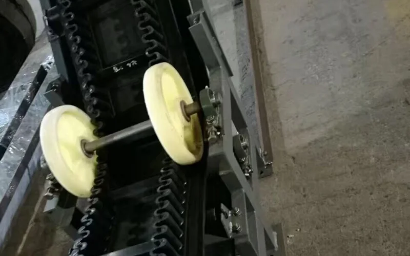
Step 6: Define Empty Margin for Steering Wheels
When the layout is Z-type or L-type, the turning pulley must be set.
At this point, a parameter specifically for steering operation needs to be defined:
Empty margin = Distance from the outer sidewall to the edge of the base belt
This width has only one purpose:
- To reserve a stable operating width for the turning pulley
The functions of the empty margin include:
- Ensuring the steering wheel only acts on the base belt
- Preventing the steering wheel from squeezing the sidewall
- Preventing the bonding area from experiencing abnormal shear stress
If the empty margin is insufficient:
- The steering wheel will contact the sidewall
- The sidewall will be forced to participate in steering
- The bonding area will crack or detach prematurely at the steering position
Therefore, the empty margin is a necessary condition for the steering structure, not a descriptive parameter.
Step 7: Substitute all parameters back into the actual layout for verification
The final step is to check each selected parameter back into the actual delivery layout:
- Does the pulley diameter match the turning pulley diameter?
- Does the sidewall interfere at the steering position?
- Is the discharge behavior controllable?
If any item does not meet the requirements in the actual layout, the selection must be reverted and adjusted.
9.Customization Matters More Than Many People Expect
In real-world projects, sidewall conveyor belts are difficult to use as standard components.
The reason lies not in the complexity of the product itself, but in the numerous operating variables, which directly affect the structural geometry.
When the geometry changes, standard parameters often become invalid immediately.
9.1 Why Sidewall Conveyor Belts Are Difficult to Standardize
In flat belt systems, bandwidth and strength often cover most applications.
However, in sidewall conveyor belt systems, the following factors change simultaneously:
- Conveying angle
- Whether the layout involves turning
- The actual fill state of the material in the pocket
- The coordination between the cleat and the sidewall
These changes are not “performance differences,” but rather differences in structural relationships.
Once the structural relationships differ, the parameters must be redefined.
9.2 Sidewall dimensions almost always require customization
The sidewall height determines the effective volume of the pocket,and the sidewall width determines its stability and fatigue behavior during operation.
Common issues include:
- Sidewall height scaled up to conveyor flow rate, ignoring material buildup.
- Sidewall width mismatch with steering wheel position.
- Sidewall forced to bend at steering positions.
These problems cannot be solved by using “higher strength rubber”; they can only be addressed by redefining dimensions and placement.
9.3 Cleat design is the most easily underestimated customization item.
In many projects, cleats are treated as “optional accessories,” which is a mistake.
The following parameters are almost never universally applicable:
- Cleat height
- Cleat spacing
- Cleat width
They directly determine:
- The effective load capacity of the pocket
- Whether material falls back at high angles
- The stress state of the cleat root
In the 45–80° range, the match between cleat spacing and flow rate is usually more critical than cleat height.
9.4 The base belt structure must be adjusted according to system variations
Even with the same bandwidth, the following parameters often need adjustment:
- base belt thickness
- carcass type
- number of plies
When the layout includes Z-type or L-type steering,
the base belt needs to simultaneously meet:
- longitudinal load
- repeated bending at the turning pulley location
If the base belt’s bending conditions are insufficient, problems won’t appear immediately, but will be concentrated and prematurely exposed at the steering location.
9.5 Empty margin is a critical geometry parameter in customization.
In systems with steering wheels, the empty margin must be explicitly defined as an independent parameter.
The empty margin is defined as:
- the distance from the outer sidewall to the edge of the base belt.
Its function is:
- to provide a stable operating width for the turning pulley
- to ensure the steering wheel only acts on the base belt
- to prevent interference between the sidewall and the steering wheel
The empty margin cannot be applied by “empirical values”;
it must be determined together with:
- steering wheel diameter
- sidewall width
- actual layout location.
9.6 Customization Directly Affects Which Outcomes?
The significance of customization lies not in “more complex parameters,” but in the results:
- The sidewall no longer becomes a failure point at the steering position.
- The stress state of the cleat becomes predictable.
- Fatigue concentration areas in the base belt are avoided in advance.
- Maintenance locations and failure modes are more focused and clear.
Conversely, in systems where parameters are copied verbatim, problems often concentrate in:
- Steering position
- Cleat root
- Sidewall bonding area
10.Why Sidewall Conveyor Belts Continue to Be Used in Incline Transport
In inclined and lifting conveyor systems, the sidewall conveyor belt is not the only belt conveyor solution.
In engineering, it belongs to the belt conveyor system category, just like the belt bucket elevator. The difference lies not in the system type, but in the way materials are carried and the path is organized.
10.1 The difference lies not in whether it’s a conveyor system or not, but in how the material is carried away.
The core differences between a sidewall conveyor belt and a belt bucket elevator are concentrated in three points:
- Whether the material is always carried by the same belt
- Whether a free-fall section is introduced during the lifting process
- Whether changes in height are completed within the same structure as horizontal conveying
The characteristics of a sidewall conveyor belt are
- The material is always located within the pocket formed by the same belt
- No material drop is introduced during the lifting process
- Changes in height are completed within the same conveyor structure as the preceding and following conveying sections
The characteristics of a belt bucket elevator are:
- The material is loaded into the bucket
- It is released from the bucket in the unloading area by gravity or centrifugal force
- The lifting section and subsequent conveying are usually two separate structural units
This is not a difference in “superiority” or “inferiority,” but a difference in structural path.
10.2 When a system aims to reduce intermediate transfer points:
In some operating conditions, the design goal is not “whether it can be lifted,” but rather:
- whether it can reduce intermediate transfer points;
- whether it can avoid the material repeatedly resetting its motion state during height changes.
In this case, the role of the Sidewall Conveyor Belt is to complete height changes without introducing additional dropping and re-receiving processes.
This is particularly important for:
- materials with a high powder content and sensitive to secondary crushing;
- systems requiring control over the discharge point location;
- continuous processes that aim to maintain a stable quality flow.
This discussion focuses on path organization, not equipment capacity.
10.3 Structural Choices within the 35–80°Lift Range
In engineering practice, the lift angle typically leads to different structural choices:
- Low Inclination Range: Flat belt, patterned belt, or low-cleat structures may be used, depending on material friction and flowability.
- 35–80° Range: Requires a clearly defined load-bearing structure to resist material slippage along the slope.
- Near Vertical Range: Often requires a bucket-based load-bearing method.
The Sidewall Conveyor Belt covers precisely this middle section, where a “clear load-bearing structure is needed, but maintaining the continuity of the belt conveyor structure is still desirable.”
This isn’t about angle advantage, but rather structural adaptation.
10.4 The Practical Significance of Layout Integration in Retrofit Projects
In existing factories or constrained sites, lifting systems often need to:
- Connect directly to existing conveyors
- Continue conveying after height changes within limited space
In this context, the value of a Sidewall conveyor belt lies in:
- It can be used with Z-type or L-type layouts
- Complete lifting and turning within the same conveyor path
- Eliminating the need to introduce new receiving structures after lifting is complete
10.5 This is a geometric integration capability, not a performance indicator.
Maintenance and operation logic remain within the belt conveyor domain
At the operation and maintenance level, the inspection logic, tensioning method, and drive type of the Sidewall conveyor belt remain consistent with other belt conveyors.
For sites already equipped with belt conveyor operation and maintenance systems, this consistency is itself a practical consideration.