This article examines multi ply conveyor belt selection from an engineering perspective, focusing on how structure, load distribution, and failure behavior interact in real conveying systems. Rather than comparing products or listing applications, it analyzes layered fabric carcass behavior under dynamic tension, impact, splicing, and environmental conditions. By contrasting multi-ply and steel cord structures using data and structural logic, the guide helps engineers judge when multi-ply designs are structurally reasonable—and when their physical limits become the dominant risk.
Introduction
To be honest, the term “multi ply conveyor belt” isn’t meant for laypeople. When you hear it on-site, during selection meetings, or in design reviews, there’s essentially one reason: someone is seriously evaluating whether this conveyor belt’s structure is reliable. It doesn’t simply mean “multi-layered” or imply marketing claims of “greater strength.” Instead, it represents a specific engineering assessment: whether a fabric carcass with multiple EP/NN ply rubber layers can effectively manage system risks.
Many ask: With steel cord belts so mature today, why use heavy-duty multi ply conveyor belts? First off, you must be loaded! The answer is actually quite simple: in many systems, engineers care more about how the system “fails” than its theoretical load capacity. Multi-ply fabric conveyor belts exhibit “predictable variations” under real-world conditions like startup, impact, maintenance, and uneven loading—not sudden failures. For engineers, the value of conveyor belt plies lies not just in strength ratings, but in their ability to anticipate how the belt will react. For procurement, it boils down to that earlier “money” issue.
This article won’t cover introductory topics like “what is ply in a conveyor belt” nor dwell on specifications like 2-ply, 3-ply, or 4-ply conveyor belt thicknesses. We focus solely on one thing: helping you determine whether a multi-ply conveyor belt is structurally sound for your specific system conditions.
1.What Engineers Mean by “Multi Ply Conveyor Belt”
In an engineering context, the value of the term “multi ply conveyor belt” lies not in the “multiple layers” themselves, but in “how the load is distributed.”
Its purpose is to distinguish a structural logic of “layered load-bearing,” not to describe the material or the number of layers.
1.1 The true engineering meaning of “multi-ply” boils down to one principle:
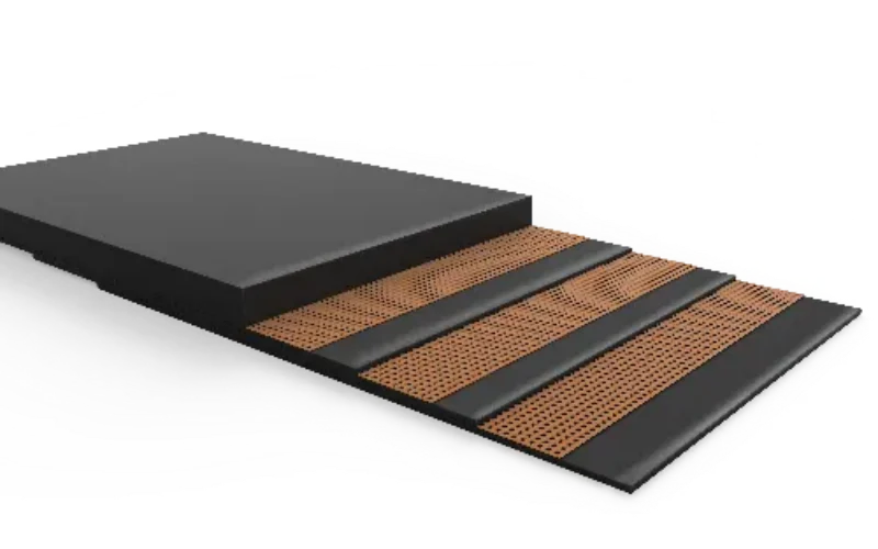
Load is distributed layer by layer through independent plies, rather than borne by a single continuous skeleton.
This is the sole engineering-significant distinction between multi-ply and other structures.
- Each ply is an independent structural unit participating in load-bearing.
- Shear forces are transferred between layers via rubber interfaces, not rigid integration.
- The structure permits stress redistribution across its thickness.
Unless these three conditions are met, the term “multi-ply” holds no engineering necessity.
1.2 Why “ply count” itself lacks engineering explanatory power
This is also the root cause of widespread specification misinterpretation.
- 2-ply, 3-ply, 4-ply are not structural types.
- Ply count merely represents parameter variation within the same structural logic.
- Changing ply count does not alter load transfer pathways.
This explains why, in engineering discussions, multi-ply and specific conveyor belt ply counts are two distinct levels of consideration.
1.3 Multi-ply is more important for “what it excludes” than “what it describes.”
In engineering documents, multi-ply is often used to explicitly exclude the following structural logics:
- Continuous integral load-bearing structures
- g., steel cord systems dominated by a single longitudinal skeleton
- Integrally woven monolithic structures
- g., solid woven belts where load paths cannot be decomposed layer-by-layer
- Non-load-bearing overlay structures
- Layers exist but do not participate in primary load-bearing.
In other words, “multi-ply” is a “load-bearing mode label,” not a material label or thickness label.
1.4 The one sentence you truly need to remember from this section
Multi ply conveyor belt = Layered, redistributable, progressively responsive load-bearing structure
If this condition does not hold, the term has no engineering utility.
2.Why Multi-Ply Belts Remain Relevant in Modern Conveying Systems
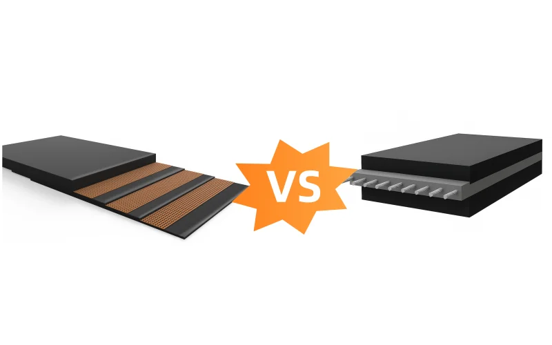
When comparing multi ply conveyor belts and steel cord conveyor belts, neither is inherently superior or inferior; it depends on which is more suitable for the specific application.
2.1 Tension-Stretch Behavior: Multi-ply belts’ “deformability” is a structural characteristic
In standard tests for fabric carcass conveyor belts (per ISO 283 / GB/T 3690),
multi-ply belts typically exhibit elongation rates of 1.5%–2.5% under reference loads,
while steel-cord belts show values <0.25%.
This data directly illustrates two points:
- Multi-ply belts
- Allow significant elastic and structural elongation
- Experience a “slower” tension buildup process
- Stress disperses more readily during startup and load fluctuations
- Steel cord belts
- Exhibit minimal elongation
- Demonstrate highly concentrated tension response
- Are better suited for long-term stable tension conditions
This is not a matter of superiority, but whether the structure requires “compromise space.”
2.2 Stress Distribution Differences Under Dynamic Loading
In systems with frequent starts/stops or load fluctuations,
the instantaneous tension peak during startup typically reaches 1.2–1.4 times the steady-state tension—a common range in engineering design.
Observations during actual operation reveal:
- Steel Cord
- Tension peaks occur briefly
- Stress concentrates at splice and drive zones
- High demands on control systems and tensioning accuracy
- multi ply conveyor belt
- Longer peak establishment time
- Multiple plies share load distribution
- Lower instantaneous stress at single structural interfaces
This explains why multi-ply belts exhibit longer service life in moderately loaded yet dynamically demanding systems.
2.3 Damage Pattern Differences Under Impact Conditions
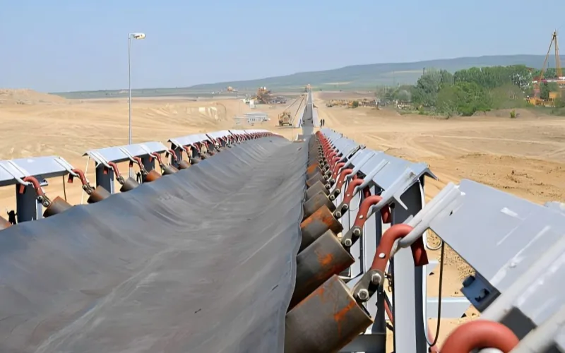
Using common transfer points with 1.5–2.5 m drop heights (frequent in ports, mines, and pre-crushing stages):
- Steel cord
- Impact stress rapidly propagates to the load-bearing layer
- Once entering the cord/rubber interface
- Structural integrity degrades rapidly
- Multi ply conveyor belt
- Impact is initially absorbed by the upper ply
- Damage propagates “single ply → multiple ply”
- Remains operational for extended periods
This explains why multi-ply belts are preferred by engineers in systems where impact dominates and tension is secondary.
2.4 Where multi-ply falls short
No product is absolutely perfect. The data above also indicates:
Multi ply conveyor belts cannot match steel cord performance in these scenarios:
- Long-term high loads near design limits
- Sensitivity to total elongation height (e.g., long tensioning strokes)
- Multi-drive systems requiring strict synchronization
- Control systems prioritizing “steady-state” performance
Under these conditions,
steel cord’s low elongation (<0.25%) and monolithic load-bearing structure remain irreplaceable.
Multi-ply belts’ inter-ply shear and cumulative deformation introduce unpredictable factors.
2.5 The True Logic of Engineering Selection Is Never About Examples
Engineering decisions on multi ply conveyor belts typically depend on:
- Whether load levels remain consistently stable over time
- Whether dynamic factors dominate system behavior
- Whether the system is more vulnerable to “instantaneous failure” or “long-term offset”
When the system requires absorbing variations, delaying failure, and tolerating uncertainty,
the data characteristics of multi-ply belts align well.
When the system demands extremely low elongation, exceptional stability, and precise control,
the advantages of steel cord become unequivocally clear.
So,the value of multi ply conveyor belts lies not in their ultimate capacity, but in the dynamic buffering capability provided by their 1.5%–2.5% elongation range;
The value of steel cord lies in the system stability delivered by its <0.25% elongation.
Understanding this, you will no longer make decisions based on simplistic logic like “what belt to use for how long a distance.”
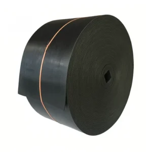
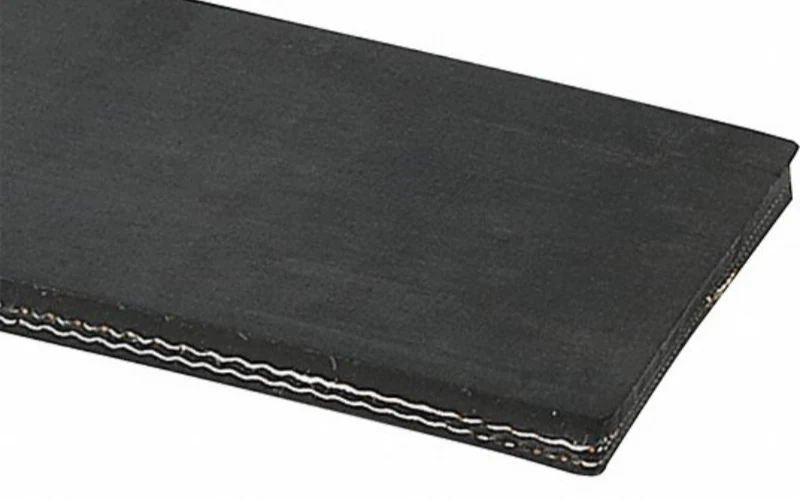
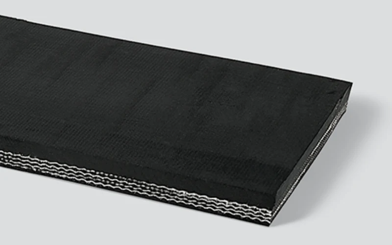
3.Typical Structural Design of Multi Ply Conveyor Belts
In this section, we’re not trying to tell you what to choose. We’re simply breaking down how multi ply conveyor belt structures work under load, and what those structural decisions actually translate to in engineering terms.
By focusing only on structure, load paths, and the data behind them, everything that comes later has a much clearer foundation.
3.1 Common ply ranges and their structural roles
In practical engineering, more plies on a multi ply conveyor belt does not necessarily equate to better performance.
Common structural ranges typically fall between 2–6 plies. Beyond this, structural benefits diminish significantly.
- 2–3 plies
- Used in low-to-medium tension systems or impact-dominant conditions
- Structural focus: Flexibility and rapid response
- High per-ply load distribution, but short interlayer shear paths
- 4–5 plies
- The most common “balanced range” in engineering
- Per-ply load distribution is further dispersed
- Balances impact, start/stop cycles, and tensile forces
- 6 plies and above
- Typically used for higher nominal tensions while maintaining fabric structure
- Structural thickness increases significantly
- Inter-ply shear and internal stress accumulation become design constraints
Engineering clarification:
Increasing ply count fundamentally alters load distribution ratios, not merely boosting strength.
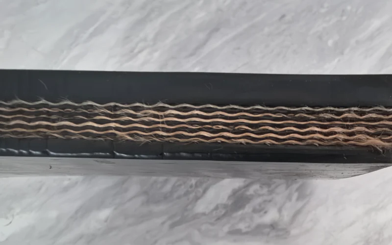
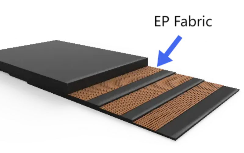
3.2 EP vs NN: True Differences in Multi-Ply Structures
In multi ply conveyor belts, EP and NN differ primarily in elongation characteristics and stress recovery mechanisms, not nominal strength.
- EP (Polyester / Nylon)
- Lower initial elongation
- Typically exhibits overall elongation around 1.5% under reference loads
- More stable tension-elongation relationship
- Better suited for systems requiring controlled tension travel
- NN (Nylon / Nylon)
- Greater initial elongation
- Elongation rate closer to 2.0%–2.5% under identical loads
- Superior impact absorption
- However, more prone to cumulative deformation under high-load, long-term operation
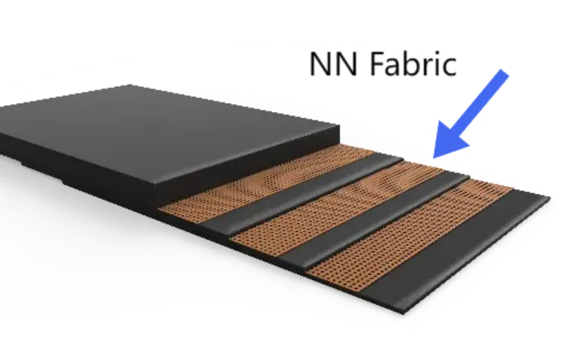
Within multi-ply structures, EP leans toward “control-oriented” while NN leans toward “cushioning-oriented.”
Selection depends on which risk the system fears more, not which is “stronger.”
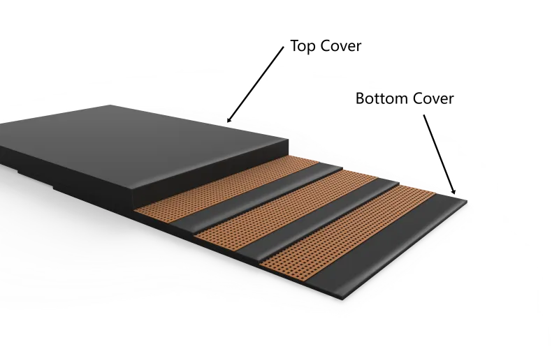
3.3 Synergy between cover and carcass, not isolated functions
An often overlooked fact:
Load distribution in multi ply conveyor belts relies on cover participation.
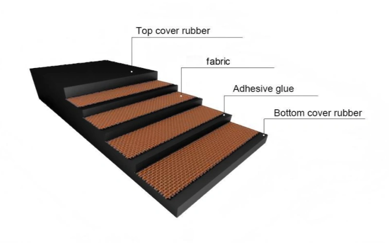
- The topcover handles:
- Impact absorption
- Initial dispersion of localized loads
- The bottomcover manages:
- Carcass stabilization
- Suppressing inter-ply shear concentration
Practical testing and operation reveal:
Excessively thin covers force premature carcass involvement in shock absorption,while excessively thick covers increase bending stress and energy loss.
This explains why engineering specifications typically adjust cover thickness in tandem with ply count, rather than specifying it independently.
3.4 Why ply count does not correlate linearly with overall strength
This is the most commonly misunderstood aspect of multi-ply construction.
Theoretically, increasing ply count enhances nominal tensile strength;
however, in actual operation, structural limits are often constrained by:
- Shear capacity between plies
- Adhesive layer fatigue performance
- Bending stress introduced by increased thickness
- Stress redistribution capacity at splices
Therefore, once ply count exceeds a certain threshold:
- Marginal contribution per ply diminishes
- Internal stresses become non-uniform
- Conveyor belts become more prone to “internal failures rather than tensile failures”
Engineering concerns focus not on “maximum tensile capacity,” but rather:
Whether loads across each ply layer remain within manageable ranges.
4.Mechanical Limits You Cannot Ignore with Multi Ply Belts
The multi ply conveyor belt structure itself has inherent limits. There are specific points where it will inevitably start to “malfunction.” These are not usage issues or quality defects, but rather the physical boundaries of the structure itself.
4.1 Tension cannot be infinitely distributed
Within a multi-ply structure, loads are indeed distributed across each ply, but this distribution has an upper limit.
When the system operates continuously at higher tension levels (typically exceeding 60–70% of the design tension), the issue shifts from “whether it will break” to:
- Shear stress between plies becomes the dominant stress
- The load-bearing capacity of plies near the neutral layer decreases
- Outer plies bear a disproportionately higher load
This explains why adding more plies in high-load systems does not proportionally increase reliability—it actually creates more uneven internal stress distribution.
4.2 Distance and speed amplify the “cumulative effect”
The structural characteristics of multi-ply composites make them sensitive to cumulative deformation.
Structural behavior changes significantly under the following combined conditions:
- Longer operating distances
- Higher operating speeds
- Prolonged continuous operation
Even if individual elongations appear small (e.g., within 1.5–2.5% ranges),
over extended operation, minute relative displacements between plies gradually accumulate, manifesting as:
- Tension system travel being progressively “consumed”
- Tension distribution becoming unstable
- Splice regions entering fatigue zones earlier
This is not an installation issue but a natural structural response over time.
4.3 Stress is not “reset” during frequent starts and stops
A common misconception is:
“After start-stop cycles, rubber conveyor belts return to their original structure and state.”
In multi ply conveyor belts, this is not entirely accurate.
- Each startup introduces a peak stress of 1.2–1.4 times the steady-state tension
- Shear forces between plies occur during startup and do not fully dissipate during shutdown.
- These shear stresses are “remembered” as fatigue.
When start-stop frequency is high, stress accumulation accelerates significantly.
This explains why systems with seemingly “low tension” often exhibit structural issues earlier.
4.4 “Adding plies” does not solve all problems
This is the most common engineering pitfall.
When the system approaches the following conditions:
- Inter-ply shear becomes the primary constraint
- Splice load capacity reaches its limit before the main body
- Frequent adjustments to the tensioning system still fail to stabilize tension
Adding more plies does not alter the load path; it only increases structural complexity.
In these scenarios, continuing to stack plies often merely delays an inevitable structural overhaul.
5.Multi Ply Conveyor Belt Behavior Under Dynamic Load
5.1 Start-Up Tension Spike and Load Build-Up
In a multi ply conveyor belt, startup is not an instantaneous process.
Field operation and calculation results show that the belt tension during startup typically reaches 1.2–1.4 times the steady-state tension. In multi-layer structures, this tension peak is not simultaneously distributed across all ply; instead, it is initially borne by the outer ply already under load, and then gradually transferred to the inner layers.
This phased load build-up prolongs the tension peak over time and disperses it structurally, but it does not eliminate it. The result is a reduced risk of instantaneous fracture, but the outer ply and splice are more likely to become fatigue initiation points during startup.
5.2 Braking and Reverse Stress Redistribution
Deceleration and braking introduce tension changes in opposite directions.
In multi-ply structures, the braking phase is often accompanied by brief load withdrawal and redistribution, during which inter-ply shear repeatedly occurs.
When braking is frequent or deceleration curves are inconsistent, this repeated shearing primarily affects interlayer adhesion and splice stability, rather than overall tensile strength. This is why structural problems first appear in the joint area of some systems, even when tensile parameters are still sufficient.
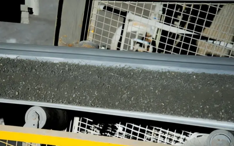
5.3 Uneven Loading and Persistent Stress Bias
Uneven loading is one of the most easily overlooked types of dynamic loads.
Off-center loading, localized material accumulation, or fluctuations in material flow can cause some ply layers to remain at higher average stress levels for extended periods.
Multi-ply structures allow this imbalance to persist for a certain period, but at the cost of: stress concentration gradually “locks” onto the same batch of ply layers, forming a stable and predictable damage path. In actual operation, this type of damage usually begins to appear in the upper ply or splice region, rather than being evenly distributed throughout the entire belt.
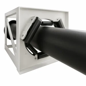
6.How Splice Design Influences Multi-Ply Belt Performance
In a multi ply conveyor belt, the splice is not a “connector,” but rather an integral part of the structure. No matter how well the main body design is implemented, the load path of the splice will rewrite the stress distribution of the entire belt during operation. This section only discusses structural influences, not construction methods.
6.1 Splice Efficiency as a Structural Constraint
In multi-layer structures, the load-bearing capacity of the splice is never “equal to” that of the main body.
The reason is simple: the splice must redistribute and align the tensile forces of the multiple ply layers within a finite length. Even if the nominal strength meets the requirements, the stress state at the splice differs from that of the main body—tension, shear, and bending will superimpose in the same area.
A stable rule can be observed in engineering:
Splice efficiency determines not “whether it can run,” but “whether the stress is concentrated on a single layer.” When efficiency is insufficient, the outer ply layer will prematurely enter a high-stress state, reducing the participation of the inner ply layers, and naturally shifting the fatigue initiation point towards the splice region.
6.2 Ply Step Configuration and Load Re-Alignment
The core issue of multi-layered structures with splices is not “how many layers there are,” but rather how these layers correctly and successfully splice.
The length, sequence, and proportion of the ply steps directly determine whether the load is transferred layer by layer or suddenly concentrated at a certain cross-section.
A more gradual step configuration allows tensile forces to be transferred over a longer distance, reducing the peak stress of a single ply;
Conversely, when the steps are too short or the proportions are unbalanced, one or two ply layers will bear disproportionate loads, becoming the structural units that enter the fatigue zone earliest.
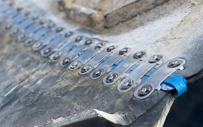
6.3 Why Failure Often Starts at the Splice
Under dynamic conditions, the splice repeatedly experiences three superimposed effects:
- Tension fluctuations from starting and braking
- Local off-center loading caused by uneven loading
- Periodic bending as the roller passes through
These effects are distributed over a long length in the body, but compressed into a finite area in the splice. The result is that even if the nominal tensile strength of the entire belt still has a margin, the splice reaches its structural limit earlier.
Therefore, splice failure does not necessarily indicate a design error, but often suggests that:
The structural role of the splice has been underestimated.
7.Environmental Factors Affecting Multi Ply Conveyor Belts
For environmental factors to affect the structure of a multi ply conveyor belt, there typically needs to be a transmission path or exposed interface (e.g., splice ends, micro-cracks in the edge rubber, cover wear-through, repair areas, cuts, edge openings after long-term wear, or even the product itself with cut edges).
If the cover is intact and dense, and the structure has no exposed channels, the impact of many environmental factors on “internal load transfer” will be significantly reduced, or even negligible.
7.1 Temperature Cycling
The core issue affecting multi ply conveyor belts is not that “heat makes rubber worse,” but rather that temperature changes alter the “deformation synchronicity of different layers,” causing stress distribution to drift.
- When the dimensional responses of the cover and carcass (fabric layers) are not synchronized under temperature changes, inter-ply shear increases, which over time will “bias” the load onto certain plies.
- This drift is not a one-time event, but rather a cyclical accumulation: each thermal expansion and contraction repeats a small stress redistribution.
Verifiable Data and Methods:
- The evaluation of rubber heat resistance/thermal aging typically employs the air heat aging method (e.g., GB/T 3512 / ISO 188), the purpose of which is to quantify the impact of the thermal environment on performance under controlled conditions.
- The heat resistance grade and related test methods for cover rubber are also clearly defined in heat resistance standards and test frameworks (e.g., GB/T 33510 / ISO 4195).
Therefore, the more intense the temperature cycling, the more important it is to treat “interlaminar shear accumulation” as a structural variable, rather than as a cause of occasional failures.
7.2 Moisture
Herein lies a physical premise: moisture itself will not “penetrate a perfectly dense rubber cover” to alter the internal load transfer.
The structural impact of moisture on multiply is typically significant only under the following conditions:
Condition A: Exposed interface/entry path exists
- Exposed splice ends or edges, and the product itself with cut edges
- Microcracks, cuts, and exposed fibers in the edge adhesive
- Microchannels in repaired or locally damaged areas
Condition B: Long-term retention conditions exist
- Moist environment + repeated wetting/drying cycles
- Moisture entrained in slurry/fine powder, forming a “perpetually wetted interface”
Under these conditions, moisture does not affect the “strength value,” but rather:
- Interfacial shear conditions (stability of the frictional/bonding state)
- Consistency of load transfer between ply (some ply bear a higher proportion of load earlier and over a longer period)
Verifiable methods and standard frameworks:
- Test methods for interlayer adhesion/adhesion between constituent elements have clearly defined standardized test paths (e.g., GB/T 6759 / ISO 252). These tests are used to quantify whether the interface can still stably transfer loads.
Therefore, the influence of moisture on load transfer is not a matter of material penetration, but rather a structural issue of “existence of channels + existence of retention + interfacial load dependence.”
7.3 Chemical Exposure
Chemical exposure often first alters the local stiffness and abrasion resistance of the cover, thereby changing the way loads enter the carcass.
Similarly, the following preconditions are required:
- Precondition A: The medium can contact the cover surface and exert a long-term effect (splash/immersion/dust adhesion)
- Precondition B: The effect causes physical changes in the cover’s properties (softening, hardening, cracking, accelerated wear, etc.)
- Precondition C: The changes in the cover are sufficient to allow impact/bending loads to be transferred to the upper ply earlier.
Verifiable engineering practices (without discussing material principles):
- Use the cover adhesive performance requirements and heat resistance/aging test framework to conduct “before and after” verification (heat aging: GB/T 3512; heat-resistant cover adhesive: GB/T 33510).
Chemical effects often manifest as “more concentrated damage locations, starting earlier from the surface,” rather than a sudden decrease in the tensile strength of the entire band.

7.4 Carcass vs. Cover: Different Response, Different Time Scale
In multi-ply structures, a stable fact is that the degradation of the cover and carcass occurs almost entirely at different time scales.
Therefore, a common “illusion” arises in the field: tensile parameters seem sufficient, but the frequency of anomalies increases (deviation, joint abnormalities, localized bulging, surface cracking, localized delamination, etc.).
To describe this rigorously, the key is to focus on “measurable variables.”
- The load-bearing capacity and elongation of the carcass/integral structure are verified using the full-thickness tensile and elongation test method for fabric-core conveyor belts (GB/T 3690 / ISO 283).
8.Multi Ply vs Steel Cord: Engineering Trade-Off, Not Upgrade Logic
Multi ply conveyor belts and steel cord conveyor belts are not “old and new,” nor are they “more advanced.” They address different types of structural problems, differing in how loads are distributed, how the system is controlled, and the form of failure.
8.1 Load Distribution: Layered Sharing vs. Unified Carrying
In a multi ply conveyor belt, the load is distributed layer by layer through multiple fabric ply layers.
Each ply layer participates in load distribution, but the proportion of participation varies with tension, dynamic loads, and time. The direct results of this structure are:
- Load can be redistributed along the thickness direction.
- Local anomalies do not immediately translate into overall failure.
- The structure is more “tolerant” of short-term shocks and fluctuations.
In contrast, the load path of a steel cord is highly concentrated:
- The main tensile force is borne by the longitudinal steel wire as a whole.
- The load distribution is stable and the path is clear.
- The system behavior is closer to a “single load-bearing member.”
Neither approach is inherently right or wrong; the difference lies in: one allows loads to flow within the structure, while the other emphasizes the determinism of the load path.
8.2 Flexibility vs. Stiffness in System Behavior
From a structural response perspective, the flexibility of multilayer tapes comes from inter-ply shear and fabric elongation.
This makes the system more resilient to changes in the following situations:
- Fluctuations in material flow
- Frequent start-stop cycles
- Unavoidable localized impacts
However, these same characteristics also mean:
- Greater total elongation
- The tension-displacement relationship is more dependent on initial conditions
- Long-term steady state is more difficult to strictly lock in
Steel cords have the opposite advantages:
- Extremely low longitudinal elongation (typically <0.3% in engineering)
- Highly linear tension response
- System state is easier to predict and control
Therefore, this comparison is essentially a flexibility vs. stiffness comparison, not a strength comparison.
8.3 Installation and Tensioning System Implications
Structural differences directly translate to the system level.
- Multi ply conveyor belt:
- Tensioning system needs to accommodate greater structural elongation.
- More sensitive to tension window and stress distribution.
- Allows a certain degree of operational deviation without immediate failure.
- Steel cordconveyor belt:
- Shorter tensioning stroke, but requires high precision.
- Easier to maintain synchronization in multi-drive systems.
- More stringent requirements for installation, control, and maintenance consistency.
The difference here is not about installation difficulty, but rather the different fault tolerance logic of the systems.
8.4 Failure Mode: Progressive vs. Discrete
This is one of the most critical differences between the two structures at the engineering management level.
- Multi ply conveyor belt:
- Common failure paths are progressive.
- Anomalies first appear in a single ply or localized area.
- Performance degradation can usually be observed in advance.
- Steel cordconveyor belt:
- Fewer critical load-bearing units.
- Limited structural margin in case of failure.
- Failures tend to be more concentrated and sudden.
Therefore, choosing which structure to use is essentially choosing whether the system needs “early warning signs” or relies more on “long-term stability.”
9.Where Multi Ply Conveyor Belts Perform Best in Real Operations
When the long-term steady-state tension of a conveyor system is significantly lower than the rated tensile strength of the conveyor belt, the structural behavior is often no longer determined by the ultimate bearing capacity, but rather by the way the load changes during operation. Under these conditions, whether the structural characteristics of the multi ply conveyor belt match the system behavior depends on a set of quantifiable operating parameters.
In practical engineering, such systems typically exhibit the following characteristics: Steady-state operating tension remains within the 40%–60% rated tensile strength range for a long period, but due to start-up tension, braking, or material fluctuations, instantaneous tension peaks repeatedly occur and are significantly higher than the steady-state level. At this point, the engineering risk is no longer focused on “whether the strength limit has been exceeded,” but rather on whether the stress is repeatedly and stably redistributed in the multi-layer structure.
9.1 Low steady-state tension, but tension fluctuations dominate the operating state.
When the instantaneous tension caused by start-up or load changes reaches 1.25–1.4 times the steady-state tension, and this peak occurs continuously throughout the operating cycle, fatigue behavior is mainly determined by the frequency of tension fluctuations, rather than by the magnitude of the steady-state tension.
Under these conditions, the multi-layered fabric carcass of a multi ply conveyor belt distributes load variations through ply-to-ply shear. The direct engineering consequence is that:
stress is not locked in a single load-bearing layer indefinitely, but rather shifts between different plies depending on the operating conditions. This behavior changes not the peak value, but rather the frequency and duration of peak loads acting at the same structural location.
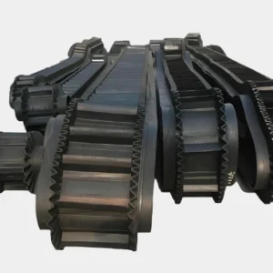
9.2 Transfer conditions where impact is the dominant load (distinguishing energy levels)
When the primary energy input to the system comes from impact rather than sustained tension, the path of the load into the carcass changes. It is necessary to distinguish between different impact energy levels, rather than using a single height range.
- When the drop height at the transfer point is approximately 1.5–0 m, and the impact zone length is finite, the impact primarily acts on the upper ply. At this energy level, the damage path typically starts from the upper structure and gradually expands in a layered manner.
- When the drop height increases to 2.0–0 m, or when the material density and particle size increase significantly, the impact is sufficient to become the locally dominant load. At this point, the stress contribution of the impact to the splice region and the upper ply is close to that of the tensile load itself.
These two height ranges are not numerical repetitions, but rather correspond to differences in structural response under different impact energy levels.
9.3 The Impact of High-Frequency Start-Stop Cycles on Structural Behavior
When start-stop cycles become the norm rather than occasional events in the operation mode of the conveyor system, dynamic behavior directly affects the structural lifespan. Here, “high frequency” is defined by time, not shifts:
- Number of start-stop cycles exceeding 20 times per 24-hour operating cycle
- Average start-stop interval less than 60 minutes
Under this operating condition, the peak start-up tension is highly concentrated in time, and the internal stress does not have time to fully stabilize. Engineering results show that: Fatigue accumulation is more likely to occur at the ply interface and splice region, rather than in the tensile direction of the entire belt.
9.4 System Conditions Requiring “Observable Degradation”
Under certain operating conditions, system management logic requires that structural degradation must be gradual and identifiable, such as fixed maintenance cycles or time lags in maintenance intervention. Under these circumstances, the multi-layered structure of a multi ply conveyor belt often exhibits the following characteristics:
- Anomalies first appear in a single ply or a localized area;
- Structural performance changes occur over a time span;
- The overall tensile capacity is not immediately exhausted;
This degradation path provides an engineering judgment window, rather than additional strength margin.
10.Common Specification Mistakes Engineers Make with Multi-Ply Belts
In the practical application of multi ply conveyor belts, the majority of problems stem from flawed specification assumptions. The following errors are highly recurring in our past projects:
10.1 Over-reliance on layers
Ignoring factors such as tensile strength, the assumption is that more ply numbers are always better and safer. Then, without changing the system conditions, the implicit risks of uncertain load conditions are compensated for simply increasing the ply number.
The structural consequences are clear:
In multi ply conveyor belts, the load is not linearly distributed according to the ply number. As the number of ply increases, ply-to-ply shear becomes the primary limiting factor. The result is often:
- An increased load-bearing proportion in the outer ply
- A decreased participation rate in the inner ply
- Premature fatigue in the splice area
The problem is not “insufficient strength,” but rather the incorrect assumptions about the load path.
10.2 Using Structure to Solve Cover Problems
Another frequently occurring error is using a carcass structure to solve problems that should be addressed by a cover.
For example, increasing the number of ply layers to combat wear and using higher tensile strength specifications to deal with impacts are based on the assumption that “a stronger structure will naturally alleviate conveyor belt damage caused by wear or impact.”
Impact and wear first act on the cover. When the cover cannot effectively distribute the load, the impact will penetrate the upper ply more quickly and directly. This type of design typically leads to:
- Premature fatigue of the upper ply
- Local delamination or splice abnormalities
- Overall tensile capacity remains ample, but lifespan is significantly shortened
10.3 Applying Multi Ply Belts to Long, Stability-Dominated Systems
In some systems, the engineering assumptions themselves are incompatible with the structural characteristics of multi ply conveyor belts.
- The system requires long-term tensile stability
- The control system is highly dependent on low elongation
- The assumption that “multi-layer structures are acceptable as long as the strength is sufficient”
Under this premise, the elastic elongation and ply interaction of multi-layer structures introduce additional variables. The result is that the tension distribution is highly sensitive to initial conditions, followed by a gradual stress drift during long-term operation, making system behavior increasingly unpredictable.
This isn’t a product problem; it’s a mismatch between the product and your system.
10.4 Quick-Fix Thinking in Belt Upgrades
The last common mistake is treating the multi ply conveyor belt as a “quick fix” for system problems. This is the most frequent issue because the most obvious problem is a problem with the rubber conveyor belt, and many people instinctively assume it’s a product issue, not considering this possibility.
This approach usually doesn’t result in immediate failure, but rather initial normal operation. Then problems arise, and the fault locations become more concentrated and harder to explain.
If you feel your conveyor belts are of poor quality no matter how many suppliers you try, then you need to consider that the problem isn’t with the conveyor belt itself, but rather with a mismatch.
11.Conclusion
The suitability of a multi ply conveyor belt is not determined by a single parameter, but by the consistency between system behavior and structural assumptions.
When the dominant risks to a system stem from load variability, frequent start-up tension, or localized impacts, and the steady-state operating tension does not consistently approach the upper limit of rated tensile strength, multi-ply fabric structures offer a manageable load redistribution mechanism, not a higher ultimate capability.
At the same time, it must be clearly recognized that in systems aiming for low elongation, long-term stable tension, or high synchronous control, the structural characteristics of the multi ply conveyor belt itself may become a limiting factor. This is not a product issue, but a problem of mismatched structural assumptions.
If, in your actual project, system conditions still do not clearly fall within the aforementioned boundaries, do not “trial and error” by increasing the ply count or strength grade.
Please provide us with the following key information:
- Belt width
- Belt length
- Belt thickness / cover configuration
- Application scenario (material characteristics, impact presence, start-stop frequency, etc.)
Our engineering team will recommend a suitable conveyor belt solution for you based on these actual operating parameters and from a structural matching perspective, rather than simply stacking specifications.
12.FAQ
1.What information is required for a multi ply conveyor belt quotation?
Answer:
A complete multi ply conveyor belt quotation must include:
belt width, total length, carcass (EP/NN + ply count), rated tensile strength, top/bottom cover thickness, and cover grade.
Example:
1000 mm EP500/5 6+3 DIN-X 100 m
If any item is missing, the quotation is technically incomplete.
2.What is the most common hidden reason a multi ply conveyor belt is rejected after installation?
Answer:
Mismatch between cover thickness configuration and actual impact/abrasion severity.
Impact: the belt meets tensile specs but shows early upper-ply fatigue or splice damage.
Action: verify top/bottom cover thickness against real material drop and wear conditions, not just standard tables.
3.Why does increasing ply count sometimes shorten the service life of a multi ply conveyor belt?
Answer:
Because higher ply count increases internal inter-ply shear stress and bending resistance.
Impact: fatigue shifts from tensile failure to internal delamination or splice fatigue.
Action: cap ply count and review shear-driven limits instead of stacking layers.
4.What single missing parameter most often makes a multi ply conveyor belt quotation unusable?
Answer:
Total belt length (endless length).
Impact: incorrect length forces on-site cutting or re-splicing, invalidating factory splice assumptions.
Action: always quote endless belt length, not conveyor center distance.
5.Why do some multi ply conveyor belts show problems only at the splice while the belt body looks intact?
Answer:
Because splice efficiency is lower than belt body strength and governs load realignment between plies.
Impact: fatigue initiates at splice long before nominal tensile limits are reached.
Action: treat splice as a structural limit, not a workmanship detail.
6.What is the fastest way to disqualify a multi ply conveyor belt proposal without running calculations?
Answer:
If the proposal lacks a clear cover grade standard (e.g. DIN-X, DIN-Y, heat/abrasion class).
Impact: unclear cover behavior leads to uncontrolled impact and wear entering the carcass.
Action: reject quotations without explicit cover standard identification.
7.Why do multi ply conveyor belts sometimes pass factory tests but fail early in the field?
Answer:
Factory tests isolate single properties, while real operation combines cyclic tension, shear, bending, and time.
Impact: internal fatigue accumulates even though each individual parameter is within limits.
Action: assess suitability based on load variation pattern, not single test values.