This guide shows you how to compute, tune, and validate conveyor belt tension from design to commissioning. It compares ISO 5048, CEMA, and DIN 22101, clarifies T₁/T₂/T₀, and explains when each method is the right tool. You’ll get field-ready formulas, worked examples, HTML-ready equations, and practical checks like sag ratio, load-cell readings, and take-up strategies. The content is grounded in standards and shop-floor practice—no hype, just what works. Expect concise recommendations, a troubleshooting FAQ, and templates that keep systems efficient, reliable, and safe.
1. Why Conveyor Belt Tension Determines Everything About Performance
In the entire belt conveyor system, conveyor belt tension is a key variable connecting “design performance” and “actual operational performance.”
The properties of the conveyor belt itself—such as tensile strength, modulus, splice efficiency, and the abrasion and heat resistance of the cover rubber—determine its ultimate load capacity; they also determine the maximum tension your rubber conveyor belt can withstand. The role of conveyor belt tension is to ensure these design parameters are correctly implemented in field operation.
- At the design level, tension controls the friction between the conveyor belt and the drive roller, thus ensuring effective transmission of driving force.
- At the operational level, tension maintains a reasonable sag ratio on the return section, preventing belt slippage or sagging.
- At the maintenance level, changes in tension reflect the stability of the equipment condition, such as changes in idler resistance, splice elongation, and the fading of the tensioning device.
If the conveyor belt tension is too low, the conveyor belt will slip, run off-track, and even reduce conveying efficiency. In severe cases, it can even cause jamming between the rubber conveyor belt and idlers or drive Pulleys.
If the tension is too high, it will lead to fatigue of the belt core fibers, overload damage to the roller bearings, and premature cracking of the joints, ultimately resulting in a lose-lose situation.
Therefore, DIN 22101, CEMA, and ISO 5048 all consider tension as a system control variable—it does not determine the strength of the conveyor belt, but it determines whether the conveyor belt can operate stably and safely within its strength range.
As ISO 5048 states:
“Proper control of effective tension is the basis for calculating the power and reliability of belt conveyors.”
2. Understanding Conveyor Belt Tension — What It Actually Means
Conveyor belt tension is a physical quantity that can be quantified, calculated, and adjusted.
As an engineer who manufactures and commissions conveyor belt systems, I focus on three core parameters during operation:
- Tight-side tension (T₁):The maximum tension at the drive roller exit, used to overcome the total system resistance;
- Slack-side tension (T₂):The minimum tension at the drive roller inlet, used to prevent slippage;
- Initial tension (T₀):The preload of the conveyor belt when stationary, ensuring sufficient friction when the system starts.
In any standard (DIN 22101, CEMA, or ISO 5048), the core purpose of tension calculation remains the same—to keep T₂ within a safe range to prevent slippage, while ensuring that T₁ does not exceed the maximum allowable stress of the belt.
You can think of tension as the system’s “mechanical balancer”:
It ensures a dynamic balance between the friction at the drive end, the gravity of the conveyed material, and the resistance of the idlers.
Once this balance is disrupted, the consequences become very apparent—belt misalignment, slippage, joint fatigue, idler roller overheating, and increased energy consumption.
This is why, in tension calculations, we always first calculate T₂ ≥ Ftotal / (e(μ·α) – 1).
Only when this condition is met can the conveyor belt operate stably and fully utilize its design strength.
3. Key Variables That Influence Conveyor Belt Tension
During the commissioning of a conveyor system, numerous factors influence conveyor belt tension.
These variables include structural parameters, operating conditions, and the physical properties of the transported materials.
Therefore, it is necessary to understand these parameters before calculating the tension.
(1) Belt Speed (v)
The higher the belt speed, the greater the system inertia, resulting in increased starting tension and dynamic fluctuations.
In high-speed conveyors, the peak tension at startup is typically 30%–50% higher than the steady-state tension.
Therefore, the starting coefficient Ks must be considered in the design.
(2) Idler and Friction Losses (f)
The friction between the idler bearings, the belt and idler contact, the resistance of the chute and cleaner, and the friction between the rubber coating of the driving roller and the contact surface of the conveyor belt,
collectively constitute the primary resistance. Both DIN 22101 and ISO 5048 calculate conveyor belt tension using the form f × L × g × (qR + qG + …).
In field maintenance, changes in idler resistance are often one of the main causes of tension instability.
(3) Material Load (qB)
The larger the conveying capacity, the higher the gravity and frictional resistance on the belt, and the greater the tension. It’s like stretching a rubber band; if someone applies pressure to the middle of the stretched band, you’ll feel the band become tighter than before.
In long-distance conveyors, material mass often accounts for more than 60% of the total system resistance.

(4) Lift (H)
When there is a height difference in the conveyor, the lift resistance directly increases the effective tension.
Uphill section: tension increases; Downhill section: gravity becomes an assist, requiring braking or damping devices to prevent tension reversal.
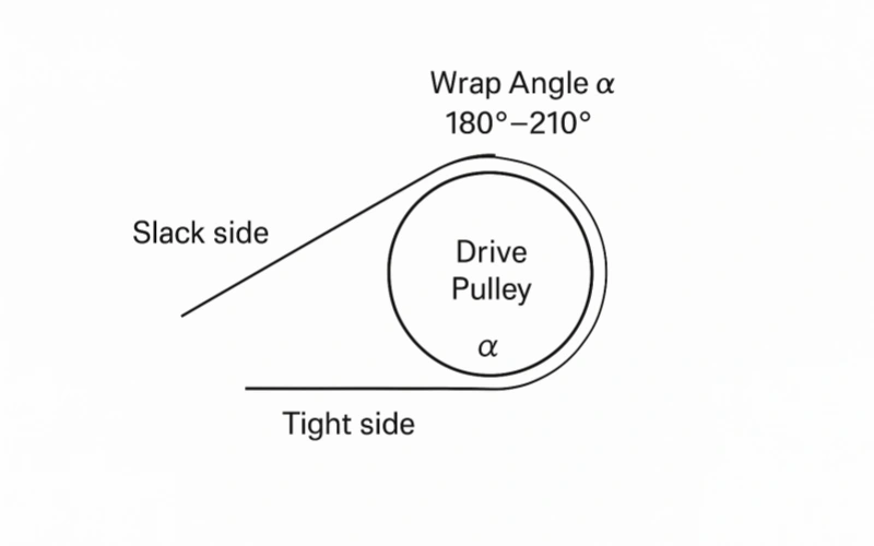
(5) Wrap Angle (α) and Coefficient of Friction (μ)
These two parameters determine the traction capacity of the drive end:
The tension ratio formula T₁/T₂ ≤ e^(μ·α) is the core relationship in all standards.
Increasing the wrap angle or improving the coefficient of friction of the roller (e.g., using ceramic coating)
can increase the driving force without increasing the tension.
Tips: Many people think the wrap angle should be 180 degrees, but many companies choose to add guide rollers near the drive roller, so that the contact angle between the drive roller and the conveyor belt exceeds 180 degrees, which can effectively increase the contact friction.
(6) Belt Stiffness and Carcass Type
EP, NN, and ST conveyor belts differ significantly in tension response.
- EP belt: High modulus but with some extensibility, good running stability;
- NN belt: Low longitudinal modulus, good transverse flexibility, strong impact resistance; Suitable for short-distance, high-drop, and frequent start-up conditions.
- ST belts: Extremely high longitudinal stiffness, uniform tension distribution, and minimal elongation; used in long-distance, high-tension, heavy-load systems. However, their complex joint structure and low tensile strength of the wire rope core make them highly sensitive to high conveyor belt tension.
Therefore, conveyor belt tension is not a value set empirically, but rather a balanced result determined by a combination of system parameters.
This is why, in the design process, any modification to any parameter (such as belt speed, inclination angle, or drum wrap angle) requires recalculation of the tension, rather than simple adjustment “by feel.”
4. ISO Method: How to Calculate Conveyor Belt Tension According to ISO Standards
In international projects, I typically use ISO 5048:1989, “Belt Conveyors — Calculation of Operating Power and Tensile Forces,” to calculate conveyor belt tension.
Unlike CEMA or DIN, ISO’s approach considers the balance between tension and power simultaneously, making it more suitable for projects requiring international certification.
The core of this method is to calculate the various resistances encountered during conveyor operation separately, and then derive the tension distribution at various points on the belt using a physical model.
4.1 Input Parameters
Before calculation, the following data needs to be collected. All parameters are in the International System of Units (SI):
| Notation | Meaning | Unit | Typical Range |
| L | Total length of conveyor | m | 20–2000 |
| H | Increase altitude (uphill is positive) | m | -100–200 |
| β | inclination | ° | 0–20 |
| v | belt speed | m/s | 0.8–6.5 |
| Im | Conveying volume | t/h | 50–5000 |
| m′B | conveyor belt unit mass | kg/m | 10–40 |
| m′Ro | Unit mass of the load-bearing section idler roller | kg/m | 20–80 |
| m′Ru | Unit mass of return section idler roller | kg/m | 10–40 |
| f | principal friction coefficient | – | 0.020–0.040 |
| μ | Roller friction coefficient | – | 0.30–0.45 |
| α | Enclose the corners | ° | 120–240 |
| B | bandwidth | mm | 500–2000 |
| g | bandwidth | m/s² | 9.81 |
4.2 Material Unit Mass
First, convert the hourly conveying capacity into mass per unit length:
This value represents the weight of material carried per meter of conveyor belt and is the basis for all subsequent tension calculations.
4.3 Primary Resistance (FH)
This portion of the resistance mainly originates from the rotation of the idlers, the bending of the conveyor belt, and the friction between the material and the belt surface.
In most cases, it accounts for more than 60% of the total resistance.
4.4 Secondary Resistance, FS
ISO categorizes local resistance as a separate item, including:
1.Feed resistance
2.Sweeper resistance: 300–800 N/unit
3.Channel resistance: 500–1500 N
4.Other devices (plow-type unloader, discharge point, etc.)
4.5 Lift Resistance, FSt
When H > 0 (uphill conveying), the tension increases;
when H < 0 (downhill conveying), the tension decreases.
4.6 Return Resistance, FR
ISO specifically emphasizes that this part cannot be ignored. Typically, m′Ru ≈ 0.5 × m′Ro.
4.7 Total Running Resistance, FU
This is the total resistance that the drive drum needs to overcome during steady-state operation of the conveyor.
4.8 Friction Factor, C
C = e( μ × α × π / 180 )
Typical values:
μ = 0.35, α = 180° → C ≈ 3.00
μ = 0.40, α = 210° → C ≈ 3.46
The larger the C value, the more sufficient the friction between the roller and the belt surface, and the stronger the anti-slip ability.
4.9 Slack Side Tension, F₂
ISO 5048 stipulates that the slack edge tension must not be less than a specific percentage of the rated belt strength of the conveyor belt to prevent slippage.
Where Sr represents the rated tensile strength per unit width (N/mm).
4.10 Tight Side Tension, F₁
This is the maximum steady-state tension at the drive roller outlet.
4.11 Power, P
P =
FU × v
1000
If we consider the mechanical transmission efficiency η:
4.12 Maximum Belt Tension, Fmax
When the conveyor has concave or curved sections:
If the layout is in a straight line, it can be simplified to:
4.13 Belt Strength Check, K
- SF = Safety Factor (EP: 8–10, NN: 7–9, ST: 6–7)
- B = Belt Width (mm)
- Sr = Rated Strength of Conveyor Belt (N/mm)
Design Requirements:
Sr ≥ K
SF = safety factor(EP: 8–10,NN: 7–9,ST: 6–7)
When this condition is met, the strength of the conveyor belt is reasonably selected.
4.14 Engineering Interpretation
From an engineering perspective, the advantages of the ISO method are its complete structure, unified calculation logic, and cross-validation of results.
It can simultaneously provide three types of key data:
- FU: Used for drive power and roller selection
- F2: Used for tensioning device design
- Fmax: Used for conveyor belt strength verification
In the international EPC projects I’ve participated in, this method is often considered a “universal language,” because it allows designers, supervisors, and manufacturers to discuss the rationality of tension based on the same logic.
5. CEMA Method: The American Approach to Conveyor Belt Tension Calculation
In the North American market, conveyor design commonly adopts the CEMA (Conveyor Equipment Manufacturers Association) standard.
Its representative document is “CEMA Belt Conveyors for Bulk Materials,”often referred to as the CEMA Belt Book.
Compared to ISO, the CEMA method is more pragmatic: it does not pursue complete physical modeling, but rather uses an empirical component tension approach as its core,
calculating the required effective belt tension (Te) by grouping and summing the resistances of different sections.
5.1 Basic Calculation Framework of CEMA
CEMA divides the tension of the entire conveyor into four main components:
TE = TL + TH + TX + TY
| Notation | Meaning |
| TL | Operating friction resistance |
| TH | Lifting resistance |
| TX | Additional resistance (scrapers, feed chutes, etc.) |
| TY | Special resistance (bending, material dropping, acceleration, etc.) |
TE (Effective Tension) is the total tension required for the system to operate.
Unlike ISO’s piecewise integration method, CEMA quickly calculates the main resistance using weighted coefficients, making it more suitable for rapid selection or preliminary design phases.
5.2 Calculation Logic for Each Item
(1) Frictional Resistance (TL)
TL = f × L × ( WB + WM )
- f: Coefficient of friction (0.02–04)
- WB: Unit weight of conveyor belt (lb/ft or kg/m)
- WM: Unit weight of material
This typically accounts for 60%–70% of the total tension.
(2) Lift Resistance (TH)
TH = H × ( WB + WM )
The change in potential energy transported on an uphill or downhill slope corresponds to the change in potential energy.
(3) Accessory Resistance (TX)
Used to calculate the additional resistance of equipment such as sweepers, feed chutes, and plow-type unloaders.
Usually given by empirical data sheets (300–800 N/piece).
(4)Special Resistance (TY)
These include acceleration resistance and curve resistance, which are used to correct transient tension fluctuations during startup.
5.3 Tension Relationship Between Tight and Slack Sides
CEMA and ISO both use the Euler equation to describe the traction capacity of the drive drum:
T1 - T2 = TE
T1 / T2 = e( μ × α )
However, in practical applications, CEMA focuses more on the minimum control value of T2.
Standard Recommendation:
T2 ≥ 0.10 × Sr × B
In other words, the loose edge tension should be at least 10% of the belt strength.
This empirical coefficient is more conservative than ISO (8% for EP/NN, 6% for ST) and is more suitable for mining systems with frequent start-stop cycles or heavy loads.
5.4 Dual Calculation of Starting and Steady-State Tension
CEMA specifically emphasizes two different operating conditions:
1.Steady-State (Normal Running) — Effective tension during the steady-state operation of the conveyor.
2.Starting (Acceleration Phase) — Transient tension during the starting phase.
CEMA Recommendation:
TE,start = Ks × TE,run
Where K8 is the starting coefficient, typically taken as 1.3–1.5.
This means that during startup, the system tension may be 30%–50% higher than during normal operation.
Therefore, this coefficient must be considered during design and selection, especially in verifying motor power, roller wrap angle, and joint strength.
5.5 Experience Requirements for Take-up Tension
CEMA also provides empirical values for the minimum pretension of the tensioning device:
Ttake-up ≥ 0.10 × Sr × B
This “10% rule” is at the heart of the CEMA methodology.
It ensures sufficient friction between the conveyor belt and drive rollers under all operating conditions to prevent slippage.
In North American mining projects, this is almost a default rule.
5.6 Practical Advantages of CEMA
From my engineering experience, the biggest advantages of CEMA are:
- Intuitive and fast calculations: ideal for preliminary design and selection;
- Mature data system: covers a large number of US-standard equipment parameters (idlers, sweepers, drums);
- Conservative safety factor: higher reliability in frequent start-stop or dusty environments.
However, it also has limitations—
CEMA assumes a linear distribution of system resistance, making it unsuitable for extremely long distances, very steep slopes, or special working conditions (DIN 22101 is recommended for such projects).
5.7 Differences between CEMA and ISO
| Comparison items | ISO Method | CEMA Method |
| Core Logic | Physical modeling + comprehensive resistance analysis | Sub-item empirical coefficient method |
| Applicable Scenarios | International industrial projects, long-distance conveyors | Sub-item empirical coefficient method |
| Calculation content | Tension + Power Balance | Tension is the main factor |
| Lower limit of loose edge tension | 6–8% × Sr × B | 10% × Sr × B |
| Start-up coefficient | Optional (Dynamic Analysis) | Must be considered (1.3–1.5) |
| advantage | Precise traceability | Fast, stable, and safe |
In North America, I often tell the maintenance team one thing:
“If the belt slips, start with tension—not with power.” This is precisely the CEMA philosophy: solve most conveyor problems with proper tension control, not with more motor power.
6. DIN 22101 Conveyor Belt Tension Calculation Method
Among the three major international standards, DIN 22101 has the most complete mathematical model and the most rigorous breakdown.
It practically defines the industry standard framework for “conveyor belt tension calculation,” and is widely used, especially in the design of long-distance conveyors and high-strength steel cord belts.
In actual projects, I often say:
“When you need to know exactly how much force the conveyor belt is bearing, use DIN 22101.”
Because it not only calculates the “total tension,” but also breaks down all sources of force step by step.
6.1 Basic Logic of Calculation
DIN breaks down the total system resistance into three main parts:
Fu = Fh + FN ± Fst
| Notation | Meaning |
| Fh | Primary Resistance |
| FN | Secondary Resistance (for cleaners, feed chutes, etc.) |
| Fst | Lift resistance |
The core of this step is to calculate the circumferential force F_u required to drive the roller using geometric parameters, mass parameters, and the coefficient of friction; that is, the required driving force value when the system is actually running.
6.2 Calculation of Primary Resistance
The Primary resistance is the largest component in the operation of the conveyor. The DIN formula is as follows:
Fh = f × L × g × [ qR + qG + ( 2qB + qG ) × cos δ ]
- f: Coefficient of friction (typically 0.02–0.04)
- L: Horizontal length of conveyor (m)
- g: Acceleration due to gravity (9.81 m/s²)
- QB: Mass of material per unit length (kg/m)
- qG: Mass of conveyor belt per unit length (kg/m)
- qR: Mass of rotating parts per unit length (kg/m)
- δ: Inclination angle (°)
This part reflects the friction of the conveyor belt on the idlers and the resistance to material movement, and is the basis for the calculation of the entire system.
6.3 Calculation of Additional Resistance
DIN does not provide a unified formula for additional resistance, but rather provides a range of typical empirical values.
Common items and typical values are:
| Item | Typical Value (N) | Description |
| Feed Resistance ( Ffeed) | ( qB \times v2 ) | Energy required to accelerate material to belt speed |
| Scraper Resistance ( Fscraper) | 300–800 | Per scraper |
| Skirt Resistance ( Fskirt) | 500–1500 | Per section of skirt |
| Other Resistances ( Fplow ) | Determined by equipment | Plow-type unloader or anti-deviation device |
Sum:
FN = Σ Fi
In engineering, if detailed data is lacking, the following is generally used:
FN=0.03 ~ 0.05 x Fh
6.4 Lifting Resistance
When there is a height difference in the conveyor, the gravitational components of the material and the belt will directly affect the tension distribution:
Fst = H × g × ( qB + qG )
- H>0: Uphill → Increased resistance
- H<0: Downhill → Assisted flow
This factor directly determines the direction of the conveyor’s power demand and is the key to distinguishing between “uphill” and “downhill” designs.
6.5 Calculation of Circumferential Force
According to the above formula:
Fu = Fh + FN ± Fst
The result represents the effective driving force (in N) required to drive the roller.
This is the “core node” of the entire calculation system; all subsequent tension distribution, selection, and power analysis revolve around it.
6.6 Euler Coefficient Calculation
The wrap angle and friction of the drive roller determine the conveyor belt’s torque transmission capability.
DIN uses the classic Euler–Eytelwein equation:
C = e( μ × αrad )
μ: Coefficient of friction between roller and belt surface (0.30–0.40)
α: Enclosure angle (radians) =αrad = αdeg × π / 180
Example calculation:
- μ=0.35,α=180°⇒C≈3.00
- μ=0.40,α=210°⇒C≈3.51
6.7 Minimum Slack Side Tension
DIN calculates the minimum slack side tension required to prevent slippage of the drive roller using Euler coefficients:
F2min = Fu / ( C - 1 )
The significance of this step lies in determining whether the system’s frictional force is sufficient to transmit the circumferential force.
If the actual slack side tension is lower than this value, the system will experience slippage or belt speed discrepancies.
6.8 Calculation of Tight Side Tension
F1 = F2min + Fu
This represents the maximum operating tension at the drive roller exit.
This value is typically close to the peak value of the conveyor belt tension distribution.
6.9 Additional tension of the redirecting roller
When the conveyor belt passes through multiple redirecting rollers, additional tension must also be considered:
Fzu = kzu × Fu
Among them, Kzu usually taken as 0.03–0.05, or using empirical values (500–2000 N).
6.10 Maximum Tension (Fmax)
The maximum tension of the system is:
Fmax = F1 + Fzu
When expanded, it appears as follows:
Fmax = Fu / ( e( μ × α ) - 1 ) + Fu + Fzu
This value is directly used for conveyor belt strength selection and joint verification.
6.11 Conveyor Belt Selection and Safety Factor
DIN specifies that the required strength of the conveyor belt should be calculated based on the maximum tension.
K = ( SF × Fmax ) / B
- K: Required bandwidth (N/mm)
- SF: Safety factor (light load 8, medium load 9, heavy load 10)
- B: Belt width (mm)
Judgment criteria:
Sr ≥ K
Sr represents the rated strength of the conveyor belt, i.e., the nominal strength of EP, NN, or ST grades.
7. How to Compare Calculation of Conveyor Belt Tension from ISO, CEMA, and DIN
During project design or belt selection phases, I’m often asked:
“Why are the results from the three standards different?”
Actually, this isn’t a matter of right or wrong algorithms, but rather differences in calculation boundaries and assumptions.
7.1 Core Logical Differences Among the Three Standards
| Comparison Items | ISO 5048 | CEMA | DIN 22101 |
| Method Type | Mechanical Model + Experimental Correction | Empirical Sub-item Method | Physical Modeling + Segmented Calculation |
| Input Data Volume | Medium | Minimum | Maximum |
| Output Content | Tension + Power | Tension-Focused | Tension + Power + Strength Verification |
| Use Cases | Industrial Manufacturing, International Projects | North American Mines, Short-Distance Systems | Long-Distance, Steep Slope, High-Strength Systems |
| Accuracy | ±10% | ±15% | ±5% |
| Calculation Time | Medium | Fast | Slowest (But Most Comprehensive) |
ISO places greater emphasis on physical equilibrium; CEMA emphasizes field experience; and DIN is the most rigorous in terms of accuracy and safety factors.
To truly understand them, you must clearly see what each standard “assumed” when calculating tension.
7.2 Typical Differences in Calculation Results from the Three Standards
Taking a typical conveyor as an example:
Conveying length: L = 150 m
Belt speed: v = 2.0 m/s
Material mass: m′G = 20 kg/m
Drum friction coefficient: μ = 0.35
Wrap angle: α = 180°
Belt width: B = 1000 mm
Rated strength: Sₙ = 1000 N/mm
After calculation using the three standards, the following results are obtained (assuming steady-state operation):
| Item | ISO | CEMA | DIN |
| FU(N) | 8,950 | 9,600 | 8,750 |
| F₂ (N) | 4,500 | 5,500 | 4,200 |
| F₁ (N) | 13,450 | 15,100 | 12,950 |
| F_max (N) | 14,000 | 15,800 | 13,600 |
| power P (kW) | 18.0 | 19.5 | 17.6 |
On average:
- CEMA results are the highest (too conservative);
- DIN results are the most accurate (most complete physical model);
- ISO results are in the middle (robust, moderate safety factor).
7.3 Differences in Safety Factors Among the Three Methods
- SFiso =6∼9
- SFcema = 8 ~10
- SFdin = 7~ 10
CEMA typically uses a higher default safety margin, thus favoring higher strength grades for conveyor belts, which, while safer, are more expensive.
DIN, on the other hand, tends to reduce redundant safety reserves through precise calculations.
7.4 The impact of parameter differences on the results
| Parameters | ISO | CEMA | DIN |
| Coefficient of Friction μ | 0.30–0.40 | 0.35 | 0.32–0.40 |
| Safety Factor SF | 6–9 | 8–10 | 7–10 |
| Dynamic Coefficient Ks | Optional | Required | Optional (Recommended) |
| Minimum Slack Tension | ≥6–8% × Sr × B | ≥10% × Sr × B | ≥6–7% × Sr × B |
| Startup Considerations | Appendix Explanation Only | Mandatory Calculation | Strongly Recommended |
7.5 Practical Application Recommendations
- Choose ISO: When undertaking export projects or multinational designs, it is the standard most easily recognized by international organizations.
- Choose CEMA: If the system is used in mines, aggregate production lines, or by maintenance personnel familiar with American systems.
- Choose DIN: This is the best option for systems with long distances, significant elevation changes, large capacity, or multiple drive sections.
In my actual system commissioning experience, I usually recommend the following:
- ISO: Calculation basis;
- DIN: Strength verification;
- CEMA: On-site commissioning reference.
Using all three in combination achieves the best balance between theory and practice.
8. How to Adjust Conveyor Belt Tension on Actual Equipment
During the design phase, we calculate the theoretical tension;
However, during operation, the actual tension of the conveyor belt depends on the type of tensioning device, its installation accuracy, and maintenance methods.
Correct tension adjustment directly determines whether the system can operate stably.
You can think of this section as:
From “calculated tension” → to “tension achieved on the equipment”.
8.1 Three Mainstream Tensioning Methods
In current industrial conveyor systems, three main tensioning methods are used:
| Tensioning Types | Features | Common Scenarios |
| Gravity Tension | Automatic adjustment, smooth response | Long-distance conveyors, mines, ports |
| Hydraulic Tension | High controllability, remote adjustment | Short-distance high-frequency start-stop system |
| Screw or Winch Tension | Low cost, easy to operate, but prone to misadjustment | Short-distance conveyors in factories, temporary systems |
All three essentially achieve the same thing:
Maintain loose edge tension F2 Within the design limits.
8.2 Tension Adjustment Logic
Although the adjustment methods of different tensioning devices vary, the core principle is the same: controlling the initial tension of the conveyor belt F0 .
The general target range is:
0.06 ≤ F0 / ( Sr × B ) ≤ 0.10
- F0: Initial tension (N)
- Sr: Rated belt strength (N/mm)
- B: Belt width (mm)
In other words, the tension should be 6%–10% of the total strength of the conveyor belt.
This range prevents slippage without causing fatigue in the fabric layers or steel wires due to over-tension.
8.3 Gravity Tension
This is the most classic and stable tensioning method.
The mass of the weight corresponds to the initial tension force using the following formula:
W = ( 2 × F0 ) / g
- W: Mass of the counterweight (kg)
- g: Acceleration due to gravity (9.81 m/s²)
Actual adjustment steps:
1.Determine the theoretical value: F;
2.Calculate the counterweight:W;
3.Adjust the height of the counterweight carriage to center its travel (generally, travel utilization is 30%–70%);
4.After no-load test run, observe the belt speed and motor current. If there are signs of slippage at startup, increase the counterweight by 5–10%.
Advantages:
- Automatically compensates for belt length changes;
- Insensitive to temperature and elongation;
- Almost maintenance-free.
Disadvantages:
- Large space requirement;
- Complex installation structure.
8.4 Hydraulic Tension
Hydraulic tensioning uses a hydraulic cylinder to provide constant pressure, thereby maintaining belt tension.
F0 = p × A
- P: System hydraulic pressure (Pa)
- A: Effective area ofhydraulic cylinder (m²)
Adjustment method:
1.Set target tension F0
2.Calculate the required oil pressure based on cylinder diameter;
3.Adjust the relief valve setting;
4.Monitor in real time via pressure sensor during operation.
Advantages:
- High accuracy, adjustable in real time;
- Supports automatic control (PLC connection).
Disadvantages:
- High cost;
- High maintenance requirements;
- If pressure is released, it can easily lead to instantaneous loosening or slippage.
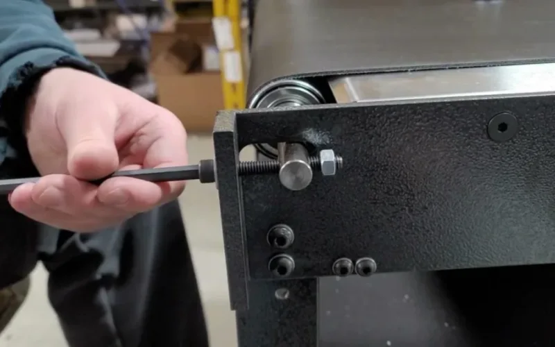
8.5 Screw or Winch Take-up
This is the most common but also the easiest way to make a mistake.
Adjusting the conveyor belt elongation ΔL by screw displacement:
F0 = E × A × ( ΔL / L )
- E: Conveyor belt elastic modulus (N/mm²)
- A: Belt cross-sectional area (mm²)
- L: Conveyor length (mm)
In actual operation, many people adjust the screw by feel, which often leads to:
- Insufficient tension → slippage and sagging;
- Excessive tension → joint tearing and idler bearing overload.
Adjustment suggestions:
- Control ΔL according to the calculated value;
- Use a tension meter or motor current curve for auxiliary judgment;
- Perform a second calibration after startup.
8.6 Common Adjustment Mistakes
| Incorrect Operation | Typical Consequences | Correct Practice |
| Blindly increasing tension | Joint fatigue, fabric delamination | Control within calculated range |
| Tensioner slide stroke too low | Cannot compensate for belt length changes | Adjust to midpoint of stroke |
| Ignoring belt elongation | Long-term sagging | Second calibration after 24–72 hours of operation |
| Tensioner roller misalignment | Belt misalignment, edge wear | Regularly check the parallelism of the tensioning structure |
Accurate calculations ≠ proper tension; true stability comes from correct adjustments and continuous monitoring.

9. Conclusion — Conveyor Belt Tension Defines System Reliability
Conveyor belt tension determines the stable operation of a conveyor system.
It affects drive efficiency, energy consumption, belt misalignment, slippage, and joint life.
Regardless of whether DIN, CEMA, or ISO methods are used, the calculation aims at only one goal—to maintain the tension within the correct range.
Correct tension comes from accurate conveyor belt tension calculation,reasonable conveyor belt adjustment,and continuous verification of how to check conveyor belt tension.
These three points are indispensable.
Ultimately, belt conveyors will not fail randomly.
Every failure is a result of incorrect tension.
FAQ — Professional Discussion on Conveyor Belt Tension