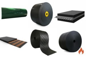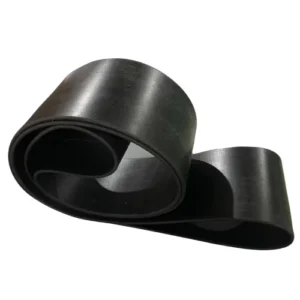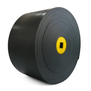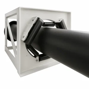
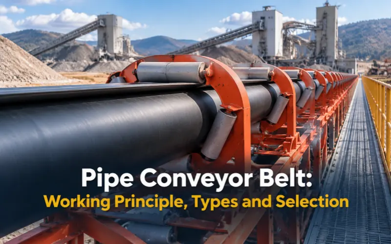
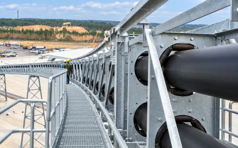
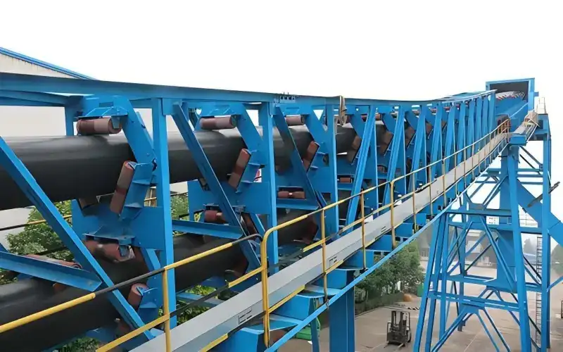
A pipe conveyor belt helps reduce dust and spillage by enclosing bulk material. It limits the load’s exposure to wind and rain. The system can follow curves and reduce the need for some transfer points. These features suit dusty materials and sites with limited space.
1. What Is a Pipe Conveyor Belt and How Does It Work?
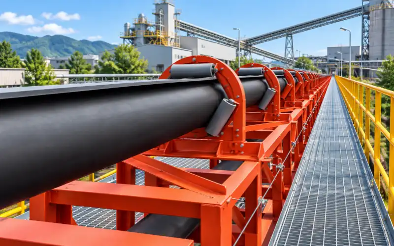
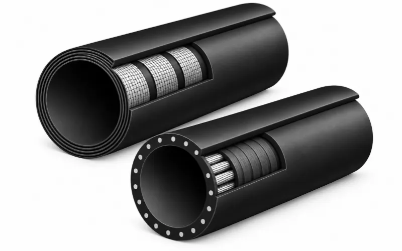
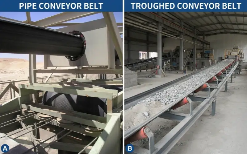
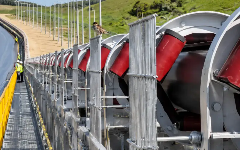
A pipe conveyor belt is a flexible rubber belt formed into a tube by idlers. Its edges overlap to enclose the material. Also called a tubular conveyor belt, it opens at the loading and discharge points so material can enter and leave.
1.1 From Loading to Enclosed Conveying and Discharge
The belt moves through four stages:
- Loading:The belt forms an open trough under the feed chute to receive material.
- Pipe Formation:Idlers gradually raise the belt edges and bring them together until they overlap.
- Enclosed Conveying:Idler sets support the closed belt and help it hold a tubular shape along the route.
- Discharge:The belt opens before the discharge pulley. Material leaves the belt as it passes over the pulley.
After discharge, the empty belt usually forms a tube again on the return run. It opens before reaching the loading area. Every circuit therefore includes forming, opening and bending around pulleys.
1.2 How the Belt, Idlers and Overlap Work Together
Three parts work together to form and support the tube:
Component | Role |
Belt structure | Carries the pulling force and provides the flexibility and support needed to form a tube. |
Forming and support idlers | Guide the belt into shape and support it along the route. |
Overlapping edges | Close the belt around the material. |
The belt structure, idler support and overlap all contribute to stable tubular operation.
The overlap is not an airtight seal. The belt opens at loading and discharge points, where you still need suitable dust and spillage controls. When reviewing the conveyor layout, check which sections enclose the material and how the transfer points will be managed.
2. Pipe Conveyor Belt Construction and Types
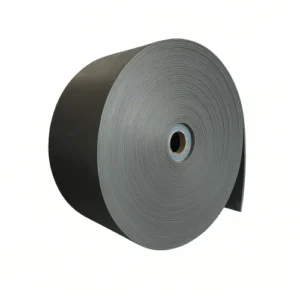
2.1 Textile Pipe Conveyor Belts
A textile pipe conveyor belt combines fabric reinforcement, skim rubber applied during calendering, and cover rubber. Warp yarns provide longitudinal tensile capacity, while weft yarns provide transverse tensile capacity. Their breaking strengths and elongation characteristics can differ.
Fabric structure also affects bending behavior. Two options to consider during carcass design are:
Fabric structure | Main characteristics | Selection focus |
SW — Straight Warp | Nearly straight load-bearing warp yarns are secured with crosswise yarns and binder yarns. | Longitudinal strength, low working elongation and a compact carcass. |
CFW fabric | Special woven reinforcement designed for low elongation, impact resistance and tear resistance. | Warp and weft breaking strengths, impact and tear resistance, and suitability for the required transverse stiffness. |
These SW and CFW characteristics are described in the supplied product brochure. 01-pdf
EP identifies polyester warp with nylon weft; NN uses nylon in both directions. SW and CFW describe fabric structures.
For your conveyor, the fabric and ply arrangement must meet the required finished-belt strength and allowable working elongation. The completed carcass also needs suitable transverse stiffness for the pipe diameter and idler spacing.
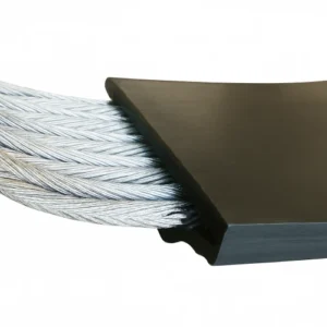
2.2 Steel Cord Pipe Conveyor Belts
A steel cord pipe conveyor belt is a strong candidate when textile alternatives cannot meet the required tension or allowable working elongation. Limited take-up travel makes elongation control especially important.
Calculate the required take-up movement from belt elongation using the actual take-up arrangement. Then check the usable travel and the selected construction’s requirements for pulleys, transitions, curves and splicing.
Rip-protection mesh is optional. Its selection depends on penetration and longitudinal-ripping risks. Any added reinforcement also needs to suit the required pipe-forming stiffness.
2.3 Tensile Strength and Transverse Bending Stiffness
These properties address different loads and failure modes:
Property | Main function | Problems when insufficient |
Longitudinal tensile strength | Carries tension along the running direction. | Running or startup tension can overstress the carcass and cause tensile failure. |
Transverse tensile strength | Resists tensile loads across the belt width. | Crosswise loads can rupture weft yarns or other transverse reinforcement. |
Transverse bending stiffness | Helps retain the pipe cross-section. | The pipe may flatten, edges may fold inward, or gaps may open between overlapping side edges. |
Excessive transverse stiffness can increase forming forces and running resistance. The belt needs to retain its pipe shape between idler sets, both empty and loaded.
Barburski’s study, “Analysis of the pipe conveyor belt pressure on the rollers on its circuit,” examines how fabric weave affects pipe closure and idler contact.
For the belt we propose, the specification must identify the carcass construction and strength requirements. Supporting pipe-forming assessments should state the diameter, support arrangement and conditions evaluated.
2.4 Overlap Design and Repeated Flexing
The belt-edge overlap is where the two side edges overlap when the belt forms a pipe. The splice connects the belt ends into a continuous loop.
The edge construction needs to form a stable overlap while the belt body supports the pipe cross-section. Two bending properties matter:
- Flexibility:transverse bending to form the pipe and its overlap, plus longitudinal bending around pulleys.
- Flex fatigue resistance:resistance to progressive damage from repeated bending.
Inadequate fatigue resistance can allow rubber cracks to develop and grow. ISO 132 assesses rubber flex cracking and crack growth; carcass and bonded-interface durability require separate evidence.
Pulley limits depend on the carcass, splice and working tension. Adhesion records should identify the tested interfaces, while fatigue results should state the method, conditions and acceptance criteria.
3. Where Are Pipe Conveyor Belts Used?
When dust escapes only at a loading chute, localized dust control may be enough. A pipe conveyor belt becomes more relevant when windblown losses or spillage continue along the carrying route. Obstacles that require changes in conveyor direction can provide another reason to consider this system.
Application | Operating Benefit | What Can Limit Suitability |
Coal and fly ash | Contain windblown fines near plant roads and equipment, reducing dust deposition and repeated cleanup. | Dry fly ash, wet ash and hot ash present different handling requirements. |
Limestone and ore | Keep scattered material away from access areas and equipment beneath the conveyor. | The largest lumps, including occasional oversize, need sufficient clearance inside the pipe. |
Cement raw materials and cooled clinker | Reduce dust release during transfer between storage and process equipment. | Check the actual loading temperature; “cooled clinker” may still exceed the selected belt’s temperature limit. |
Routes around existing plant structures | Follow feasible curves around obstacles, potentially eliminating some transfer points and their associated spillage. | Curves need suitable geometry, while forming transitions and maintenance require adequate space. |
Protecting the material matters too. Rain can change feed moisture, while outside debris can contaminate material headed for processing. If either affects storage or production, enclosure offers value beyond a cleaner site. This protection applies to the enclosed carrying section; loading and discharge still need appropriate material control.
For hot material, enclosure also changes heat dissipation. Open-belt temperature experience alone therefore cannot establish suitability. Likewise, containing a wet or sticky load does not resolve its discharge behavior. These limits help you decide whether pipe conveying addresses your operating problem before moving into detailed belt selection.
4. How to Select a Pipe Conveyor Belt for Your Conveyor and Material
4.1 Start with the Conveyor Design and Equipment Limits
Existing Equipment | Belt Property to Match | What a Mismatch Can Cause |
Pipe diameter and forming-idler dimensions | Belt width and belt-edge overlap | Insufficient overlap or interference where the edges meet. |
Idler spacing and arrangement | Transverse stiffness | Flattening or inward folding between idler groups. |
Pulley diameters | Belt and splice bending requirements | Excessive bending stress in the carcass or splice. |
Horizontal and vertical curves | Carcass construction and transverse stiffness under operating tension | Uneven forces and an unstable pipe section. |
Forming and opening transition lengths | Carcass flexibility and allowable edge strain | Excessive edge strain as the belt forms or opens. |
Working tension and available take-up travel | Rated strength and expected elongation | Insufficient strength or exhausted take-up travel. |
Drive capacity | Belt mass and running resistance | Insufficient power or difficulty starting under load. |
4.2 Check Capacity, Lump Size, Pipe Diameter and Belt Width
Divide mass flow by loose bulk density and belt speed to calculate the required material cross-section, using consistent units. Use density measurements from feed samples covering the moisture and particle-size changes you actually encounter. Check capacity at the lowest measured density within that operating range. At the same tonnage, this condition requires the most space.
Compare the result with the permitted filled area in the conveyor’s original capacity calculation. Check the largest lump that can reach the belt, including occasional oversize. If rare large pieces determine the required pipe size, upstream screening or crushing may avoid changing the conveyor.
A wider belt on the same pipe diameter mainly changes belt-edge overlap; it is not a straightforward capacity upgrade.
4.3 Match Carcass, Strength and Elongation to the Tensioning System
The strength rating specifies breaking strength per unit belt width. Working tension is kept lower to leave a margin for splice performance and repeated loading. Find the maximum design tension and safety factor in the original conveyor’s tension calculation or belt specification. The tension calculation should cover starting and stopping. If these values are missing, the conveyor manufacturer or responsible design engineer should confirm them before you change the strength rating.
Next, compare expected belt elongation with the take-up travel still available. The take-up needs room to keep the belt tensioned as its length changes. Have the designer calculate the required movement for your take-up arrangement. If travel is insufficient, compare a lower-elongation belt with modifying the take-up. A steel cord pipe conveyor belt becomes a practical option when textile alternatives cannot meet both the tension and take-up requirements.
4.4 Match Transverse Stiffness to the Pipe, Idlers and Route
- Insufficient transverse stiffness:the pipe can flatten or fold inward between idler groups, disturbing belt-edge overlap.
- Excessive transverse stiffness:the belt needs more closing force, which can increase idler loads and running resistance.
Use forming data for the proposed belt width and pipe diameter. Check whether the pipe maintains its shape and suitable contact with the idlers. Review the curves and belt-tension range for both empty and loaded running. Compare candidate constructions using the same test method and forming geometry, because width, diameter and overlap affect the results.
4.5 Select Cover Rubber for the Material and Environment
Material or Environment | Cover Rubber Requirements |
Abrasive material | Abrasion resistance, plus cut and tear resistance where particles have sharp edges. |
Hot material | Heat resistance matched to loading temperature and enclosed conveying conditions. |
Compatibility with the identified substance, including concentration and contact temperature where relevant. | |
Flame-retardant and antistatic performance meeting the site’s specified safety requirements. | |
Outdoor exposure or low temperatures | Weathering resistance, ozone resistance and low-temperature flexibility. |
For hot material, provide continuous and peak temperatures at loading, together with the duration of temperature peaks. The enclosed carrying section changes how heat escapes. Select the heat-resistant cover for that exposure and the time material remains on the belt. A temperature rating used on an open conveyor should therefore be checked for pipe conveying.
4.6 Confirm the Proposed Belt and Splice Compatibility
The proposed pipe conveyor belt specification should include:
- Belt dimensions, carcass construction, rated strength and cover rubber.
- Pipe diameter and required belt-edge overlap.
- Pulley diameters and transition lengths required by the proposed construction.
- Splice design, finished dimensions and on-site joining method.
- Where needed, forming or stiffness results for the proposed construction, with test conditions stated.
Check the finished splice width, thickness and bending requirements against the forming idlers and pulleys. Confirm that the installation equipment can produce the specified splice. Forming tests can show pipe shape and idler contact under their test conditions; they do not establish running stability through every curve on the conveyor.
5. Pipe Conveyor Belts vs Trough Conveyor Belts: Benefits and Costs
Compare belt price and the cost of the transport task separately. A belt quotation needs a defined width, strength, cover specification and splice scope. A conveyor comparison needs the same throughput, endpoints, lift and operating hours. Equal belt width does not mean equal carrying capacity, so price per meter alone cannot determine which system costs less.
Comparison Area | Possible Cost Effect | What to Include |
Cleanup and material loss | Enclosure may reduce recurring cleanup and unrecovered material. | Cleanup labor, disposal charges and the value of material actually lost. |
Routing and transfers | Fewer transfer points may avoid some chutes, conveyor drives and dust-control equipment. | Equipment required by each feasible layout, including forming sections and idler supports. |
Belt purchase and replacement | Pipe-specific construction and splice work can increase replacement expense. | Delivered belt, splice materials and labor, installation equipment and shutdown time. |
Electricity | Running resistance can offset savings from fewer transfer drives. | Total annual electricity use across all conveyor sections at comparable throughput. |
Pipe forming and friction within the belt-edge overlap contribute to running resistance. Belt–idler contact also creates indentation rolling resistance as the cover rubber deforms. These losses help explain why enclosed conveying should not carry a blanket energy-saving promise. Compare calculated or measured electrical input over the expected operating hours, including transfer equipment in each layout.
For belt purchasing, separate the delivered belt price from the installed replacement cost. A cheaper roll can lose its price advantage if installation takes longer or the splice requires additional site work. Keep service-life assumptions explicit; without reliable operating records, a promised longer life should not be counted as a confirmed saving.
Where a troughed arrangement meets the same containment and routing requirements, it may be more economical. A pipe conveyor belt’s additional expense is easier to justify when reduced cleanup, material loss or transfer equipment makes a measurable difference.
6. Common Pipe Conveyor Belt Problems and Performance Checks
Belt twisting moves the overlap around the pipe; overlap opening separates the overlapping belt edges. Record them separately if both occur. Also note where each problem starts and whether it changes between empty and loaded running.
Observed Problem | Conditions to Check |
Curve geometry, off-center loading, belt tension, idler arrangement and belt construction. | |
Belt-edge overlap opening | Available overlap, transverse stiffness, idler support and whether the pipe is overfilled. |
Local flattening or collapse | Stiffness relative to pipe diameter, spacing between idler groups, tension and actual loading. |
Belt forming and opening, finished splice dimensions and contact with surrounding equipment. | |
Increased running resistance or power consumption | Throughput, belt speed, temperature, idler condition and whether the belt is still running in. |
I would check local idler support and loading when a symptom repeatedly begins at one conveyor location. When it travels with one belt section, I would also check that section and its splice. These patterns help narrow the investigation. Rotation can involve several interacting causes, so changing one belt property may leave the underlying problem unresolved.
Forming tests show whether a sample holds its pipe shape. Contact-force measurements show where support is lost or loads concentrate, even when the section appears closed. These results help compare candidate belt constructions under the tested conditions. They provide more useful selection evidence than simply showing that a belt can be rolled into a tube.
7. What to Confirm Before Replacing a Pipe Conveyor Belt
Gather the original belt specification, splice drawing and conveyor layout. Include pipe diameter, belt width, length, carcass, strength, total thickness and cover specification. Use the original cover thicknesses; measurements from a worn belt show only what remains. Mark equipment modifications on the drawings so the replacement is checked against the current conveyor.
Compare today’s material and operating conditions with the original design. State the design and current temperatures, maximum lump size, throughput and belt speed. For unresolved problems, attach photographs with the conveyor location marked and describe when the problem occurs. This information helps determine whether the original specification should be retained or revised.
Coordinate delivery, installation and splicing with the planned shutdown. Confirm reel access, available splicing equipment and the installation crew. State the finished belt length and required splice allowance separately. Confirm equipment compatibility for any change in carcass, width or thickness.
Agree with the conveyor engineer on the expected pipe shape, overlap position and stability during empty and loaded running. Compare power readings at similar throughput, belt speed and temperature. A new belt may require more power during break-in, so keep commissioning readings separate from subsequent operating records. Use the readings over time to assess performance against the agreed requirements.
8. Conclusion: Match the Belt to the Conveyor and the Material
A pipe conveyor belt needs to match your material and conveyor. Forming a tube alone does not guarantee stable operation.
Review your belt specification, conveyor drawings and current operating data with the belt manufacturer and conveyor engineer to confirm the replacement.
9. FAQs About Pipe Conveyor Belts
9.1 Can You Splice a New Section into an Aged Pipe Conveyor Belt?
A section replacement may be feasible when damage is localized. However, aging can change the retained belt’s transverse stiffness. A new section made to the original specification may therefore form differently, creating uneven contact forces and rotation. I would compare samples of the retained belt and proposed replacement, then check their carcass and splice-material compatibility. Widespread carcass deterioration favors full replacement over repeated section repairs.
9.2 Can an Existing Pipe Conveyor Run in Both Directions?
Reversible conveying requires a system designed for both directions. Reversing the motor alone does not establish that capability. Direction changes can affect belt tracking and overlap stability. The transition sections, loading points and cleaning arrangements also need to support reverse operation. Have the conveyor designer confirm these functions and the drive and tensioning requirements. A different belt specification alone cannot make an existing conveyor reversible.
9.3 Will Existing Rotation Sensors Work with a Replacement Belt?
If your system reads embedded magnetic markers, the replacement belt needs the specified marker layout. Replacing a belt section can interrupt that layout and undermine detection. Include marker positions and splice-area requirements in the order. For camera or distance-based systems, I would check calibration against the new belt’s actual profile and overlap position. Verify detection at every monitored location after the change.